Thursday, 23 January 2025

First circuits of the railway achieved

 Well, having made the baseboards, I got going on building the railway itself. Firstly, I will talk about the layout. The main station is taken from the layout that I started building in the flat. I liked the layout and had covered its use on the computer so it made planning a bit easier. The track then runs round the back of the garage onto the other side which is a fiddle yard of one track off the main.  The main then continues round over the bridge (which is removable)  back onto the station board again. Where there was a little head shunt at the end of the platforms on the old layout is now a connection to the branch station. This track crosses over the board at the back of the garage but slopes down about 1 1/2 inches in to the branch station. The branch station is set on a baseboard that is below the fiddle yard - to give a separation from that. The branch station will have a runaround and a single track into the goods yard. The traffic will be mostly coal but with the occasional general goods and cattle going out.

Here is a sketch of the plan. I will put up a proper Anyrail image later when the track plan is really sorted as I only have the main loop set up on Anyrail at the moment.


Here is a shot of the undernea th of the main board which gives a good indication as to how the electrics/electronics are going to be sorted. 


We have the main track bus - the thick red and black wires which are connecting all the areas of the track to ensure full connectivity for the DCC signal. The point motors are all DCC Concepts IP Digital and are currently wired incorrectly in the photo. I assumed that I could connects the motors with the black and red in the first two sockets and the frog in the third. Wrong! More a bit later. 

I continued all around the layout with the main track bus. Doing something that I couldn't do before, I put in an Accessory bus to connect the point motors to the DCC Concepts ESP® Wireless DCC Receiver Unit. I have a nice control box using DCC Concepts point levers that is connected wirelessly to this unit.


I got all the track wired up along with the point motors but nothing worked!
As shown in the image below, there is a right and a wrong way to connect the IP Digital point motor to the main buses when you have an accessory bus as well as a track bus. Basically, you need to connect the accessory bus wires to sockets 1 & 2. This provides the digital instructions from the DCC system to the point motor. Then you connect the track bus to sockets 4 and 5 so that the frog wire, that goes into socket 6, can get the correct feed when a short occurs as a loco runs through the point. 

I, stupidly, thought that just the track bus to 1 & 2 and then the frog wire to 3 would work but that was wrong. Nothing worked. I thought for a couple of days and worked it out.


After I had got all this working, I had to finish laying the track for the whole loop line. It was only the two tracks from the left hand  point on the "fiddle yard" through the right hand point and the last connection to the removable bridge. That done, I started to test it all to find that the last point - the right hand one on the "fiddle yard" - didn't work. I spent two days trying to work out why the one point was a failure. Finally, on tracing the wires, I found that the white lead from the point to the accessory bus had never been connected! In fact, it had never even been stripped. It was as it was after being cut off the reel! Once, I stripped and connected the wire to the appropriate bus it all worked.

Well, that is where I am now. I have a single track loop all around the garage with a double track through line fiddle yard. Exactly what I wanted so I can now start to, firstly run trains and, secondly start to lay the main station.


If you look at the back of the room, you can see a glass display case. This has all of my scale plastic models that I have built over the last few years. It is destined to be placed right at the back of the room in front of the two tracks that link both sides of the main track. However, I have been thinking about this and now plan to purchase 5 40cm wide glass fronted cabinets to fit on that back wall. Then, we can get rid of the display cabinet and have the floor clear.


Tuesday, 26 November 2024

Even Bigger Changes


 I have got on quite well with the railway since the last post but everything has come to a dead halt. 

We have moved from our apartment into a nice two bedroom bungalow. Now my original plan, before the current house was found, was to use the 2nd bedroom as before as my mother-i-law has gone into a care home so I was to get my hobby room back. However, the bungalow that we found has a 28' garage that has been insulated and fitted out with lighting and electricity sockets. Well, it couldn't be any better, could it!

Mind you, once moved in, the garage was full of shelving and cupboards leaving not a lot of room for the railway. This was going to be restricted to being on two tables of 750x1800mm which wasn't much better than squashed into a side of the living room in the flat. A big rethink was required!

The new plan was clear out the whole garage and get rid of as much as I could. Valerie's cupboard of Jigsaw puzzles was emptied and the jigsaws found homes in various cupboards in the house. My cupboard was emptied along with the shelf unit down the back of the garage. The idea was "if it hasn't been used in 6 months then I either don't want it or it is for a long term project". Even unopened bottles of Woodland Scenics flock went as they were taking up space and were easily replaced when needed.

The next step was to put the two cupboards and the shelving  unit on Facebook. They were snapped up. They turned up with a van and it was all gone!

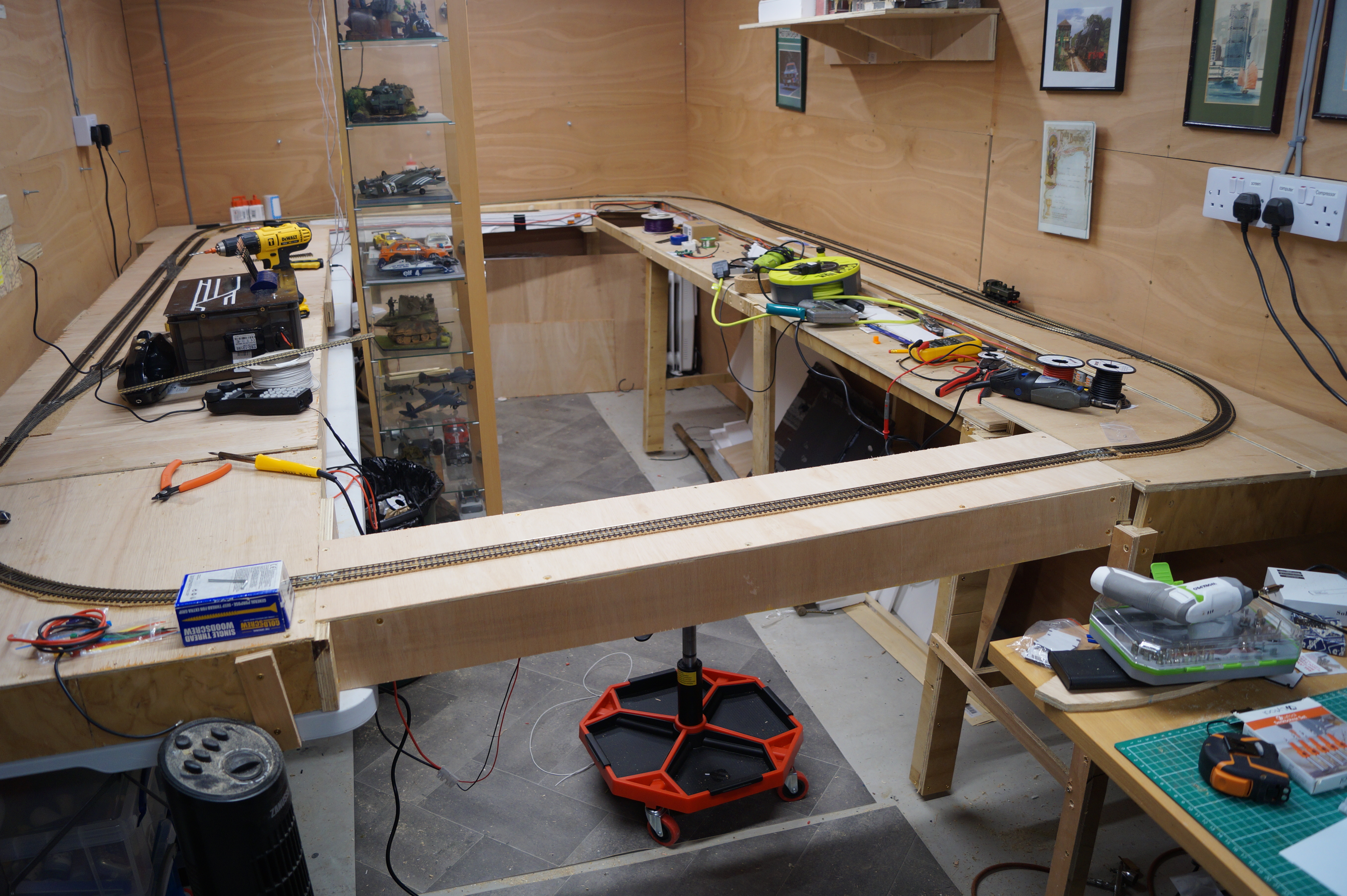
My next step was to build the baseboards. The plan is to have the original station from the flat on one wall. Well, not the original flat but a rebuild on plywood rather than on foam core. The railway will then run behind my scale model display case over to the other side of the garage where there will be two levels. The same level as the first board will be for the fiddle yard which will be double ended so trains can go straight through on one line and be swapped about on the other. The front of the board will be a little bit lower and comprise a nice little branch line ending. The through line will then return over a removable  bridge.


The boards, as you can see, are all in place and ready for track laying.

To be continued....


Tuesday, 27 February 2024

Running In

 With everything working electrically, it is now time to test out some of the plans that I have for the railway. Initially, I wanted to try out the passenger side as I had bought some quite old Hornby "blood and custard" coaches to run with the Accurascale Manor 4-6-0.

Ok so first off, there was a problem with the Hornby coaches. They had what the hobby calls "pizza cutter" wheels and wouldn't go through the points so I had to buy a pack of Bachmann replacement wheel pairs. These fixed that problem. Then, I was having difficulty uncoupling the first coach from the loco as the coaches had the old type of coupler - the whole width of the coach - and my hand uncoupler was causing derailments. The answer to this was to replace the couplers with Kadees.

Brett at the LHS sold me some NEM Kadees and some little NEM sockets that were supplied by Golden Valley. These seemed like a good idea in that you just glue them to the floor of the coach and plug an NEM coupler in. However, they interfered with the bogies and were too high to couple properly to the Manor. The Manor had NEM sockets so it was easy to remove the existing couplers and replace them with Kadees so that was the benchmark height.

The floor of the coaches was very high so I had to pad out the base to get the couplers to the right height. I used the Golden Valley adapter on one coach but it needed cutting about and padding out so it was a bit of a faff so I dug out some Kadee no. 5s for the other two coaches. Here is how it looks - not nice but it all works. First the Golden Valley NEM set up.


Now, the No. 5s much neater.


Once I had the couplers sorted, it was time to run some trains. I have three passenger trains planned for the routine. One will be a 64XX with an auto coach. Then there will be a 64XX with two local passenger coaches. Lastly, there will be the weekly holiday train which will be the Manor 78XX with three Mk 1 coaches - 2 brakes and one full coach. The theory is that these three coaches came off a London to Cornwall train (led by a Castle presumably) and were brought down from the main line by the Manor. Here is what it looks like with two of these in.


I did, however, uncover two problems that interfered with the successful running of the trains. First off, there was an issue with the Manor transitioning from the main baseboard onto the fiddle yard board. It seems that there is a rise in the track at the edge of the board that is causing the Manor to slip its wheels.  Also, the long Mk.1 coaches don't much like the join either. I need to do some work on the join between the two boards to get rid of this. Secondly, the Digitrax controller isn't acting normally when there is a short. Normally, if I run a point the wrong way round, there is a short which clears itself when the loco is moved to clear the point. This is not happening and I am having to turn the Digitrax box off, wait 5 or so seconds, and turn the box back on. 

(Aside: needless to say, the point of the levers is that I can see how each point is set so that shorts shouldn't happen - as in a real signal box - but I still do it!)

I put a question up on Model Railroad Hobbyist where the answer seemed to be a fault in the Digitrax controller. However, I thought about this and I think it has more to do with the way that I have wired in the ESP radio receiver for the point levers. I just put the ESP board in between the controller and the power bus which makes it susceptible to the short. I think that I have to put in a separate accessory bus so that the short doesn't get to the ESP board. In any case, I am checking this ideas out with DCC Concepts so we shall see what we see. Here is the current and proposed layouts.


There will be more on this, I can promise.


Thursday, 22 February 2024

Ballasting and a backscene

 I told myself that I wouldn't put ballast down on this railway as I have always made a mess of the process before ending up with points that were stuck. However, I found myself carrying out the task the other day. I took it nice and slowly making sure that I avoided the switching part of each point. In fact, I actually enjoyed the process, which took about 5 days - so you can see how slowly I took it.


Having got all the ballast down, I repainted the rest of the boards in the Hobbycraft brown.

As you can tell, I have also added a backscene to the boards.  This is one of my foamcore processes. 

As you can see in this image, I cut a piece of foamcore and create tabs sticking downwards. Once, the whole lot is complete, I hold each panel up against the back of the main baseboard and create some slots for the tabs to slide into. This way, I can remove the backscene when I need to turn the main board over to work on the underside.

Now, we come to the downside. I bought a backscene from my LHS - Model Scenery Supplies Backscene 206B - which comes as a roll of 3m long and 380mm high. I cut off some of the height. Now we come to the problem (which you can see on the shot of the whole board above). I can't use the normal method of glueing the paper to the board as PVA has lots of water as a component and this would make the foamcore  warp - I have been there before. Hence, I use strips of double sided tape - four lines along the length. The problem is that it is very sticky so you get one go at it. As you can see, that one go one the first board along the back resulted in some bumps that couldn't be ironed out. I ended up cutting along the bump and re-sticking it down. It looks dreadful. 

This taught me a lesson so, when I did the next board, I glued about 4" down at a time. This seemed to work quite well and, hence, the last two boards were a success. I have ordered a replacement roll from Orwell's, which should be here on Friday. I have changed the order, under Brett's instruction, to their premium brand, which comes as vinyl rather than paper and is pre-glued. We shall see how we get on. Fortunately, because the backscene is in four pieces, I can replace the bad bits easily.

I have also bought some 1" Velcro self adhesive front and back. Once I have got the backscene sorted, I will place a 6" length of Velcro across each joint at the top. I will then cut that at the join leaving 3" on each side. Using the other component of the roll, I will cut out a 6" length of that and use it to fix the  two boards tightly together.

Lastly, I tried the track out with some of my locos. First off, the track needed a lot of cleaning - high grade emery loaded with Track Magic eventually got most of the muck left over from ballasting off the top of the rails. Three issues emerged. 

  1. One piece of track had lost its connection to the track bus so I had to make a temporary connection using crocodile clips.
  2. My latest loco - a 94XX from Bachmann - was misbehaving. It is fitted with a Next18 decoder from Accurascale - the one that came with my Manor. It jerks three times on starting and stopping which makes it difficult to use. I will take it to Orwells tomorrow to get Kevin to have a look at it. I expect that I will ask him to put a Zimo decoder in as a replacement.
  3. The DCC Concepts levers stopped working. I messed about taking the power off and on, etc. but nothing fixed it so finally I took the lid off the lever box and saw that all the pilot lights were out. The battery had run down! It didn't show externally, as there was enough power to keep the LED on the panel working but not enough for the boards.

All three issues will be resolved easily. 1 and 3 are already sorted and 2 will be fixed tomorrow.

Sunday, 28 January 2024

Trouble with Locos

 Since changing over to British OO I have purchased 4 locos. 1 45XX small prairie, 1 64XX pannier, 1 15XX pannier and Iford Manor 2-6-0. The 45XX and 64XX were both Bachmann whilst the 15XX was a new release Rapido and the Manor was an Accurascale model. All four are very nice models except the Rapido and the Manor were exceptionally detailed. But...

The 45XX and 64XX were bought from my local shop - Orwell Model Railways.

The 45XX was an indifferent runner and had no traction at all. It seems that, with these prairies the front and rear wheel sets often were badly adjusted and kept the main driving wheels a bit too proud losing traction. Eventually, it barely moved so I have decided to sell it. Rails of Sheffield have offered an indifferent price but they keep their word so it's off to them tomorrow.

The 15XX was bought from Rails. First off, the front steps fell off - no I didn't break them, they just fell off so I had to glue them back on. Then it stopped running and was returned to Rails. They sent me a new one.  On removing the body, the smokebox fell off - same comment as above. The glue area had a solid line of white glue around it so it obviously had never been glued properly. Then the 2nd loco stopped working. On exchanging e-mails with Rails, I sent them a video of the 64XX and the 15XX to show how the track was clean and fit for purpose and how the 15XX didn't work. I told them that I was rejecting the model as I wasn't prepared to have this one returned to Rapido with all the delays that would happen. They accepted this very nicely and I am getting a credit note. I think that I will use it to get a 94XX Bachmann pannier. It is a pity because I had it fitted with an ESU sound chip that I was given at the Warley show.

The 64XX is a nice little runner and I have been able to use that as a yardstick against the 45XX and the 15XX so not much more to say. The Manor is a lovely piece of kit and seems to work fine on my 8' long station layout.  As I now have a Next16 sound chip going spare, I am off to Coastal DCC tomorrow to get Kevin to set it up for the Manor.

Lastly, as a replacement for the 45XX, I used some Christmas Amazon vouchers to purchase a Dean Goods 0-6-0 from Oxford Rail. This is a nice little loco but the only one that I could get on Amazon was a War Department version. I need to get all of the markings off and renumber etc. for a 23XX. Railtec have a nice scheme where they print on demand after asking me lots of questions to which I didn't know the answers. I got there in the end so we shall see how it comes out. When I bought the loco, I also ordered an 8 pin wired decoder to go with. Unfortunately, the space in the tender for the decoder is very small and the decoder that I purchased didn't fit. Fortunately, being Amazon, it is going back and I will, again, take this up with Kevin tomorrow as I think that a tiny Zimo will fit.

So, all this started in September last year and, hopefully, might be over in a few days.

Two comments - about Rapido and Accurascale. Rapido's 15XX is a nice little loco with wonderful valve gear but manufacturing needs a bit of look at as bits fell of and the mechanisms didn't work at all well. Accurascale make wonderfully detailed models but you do pay for them. The Manor looks to be worth the money but we have to wait and see when I begin to run it regularly. I have also bought one of their Siphon G vans. This was expensive for a van and all I got that seemed to justify the price was some hugely detailed undercarriage. As most of this can't be seen, it seems to me that it could have been made cheaper but then I am not fully into modern demands.

That's it. Hopefully, in a few days, I will have a full compliment of locos that all work as expected. Let's wait and see.

Friday, 19 January 2024

Signal Box Levers

 When I was at the Warley show in November I was watching a layout supported by my local model railway/DCC shops - Orwell Model Railways and Coastal DCC. This layout was Long Melford, which was featured in Model Rail magazine recently. The bit that I liked was the bank of levers for the signal box - AKA point and signal control.  These levers were a DCC Concepts product and I vowed to get some for my railway. As Christmas was coming, I persuaded the wife to buy me a box of 6. I had already bought a single one to test out. As I only have seven points this was going to be fine. 

However, it was clear that there were going to have to be 21 wires between the levers and the railway and I couldn't think of how I was going to connect these up because there was nowhere on the layout that I could put the lever frame so it would have to be a stand alone box. I had spoken to Richard from DCC Cncepts at Warley about how to make a mimic board and he told me about their ESP transmitters and receivers. At the time, I thought that he was just suggesting these because of their cost but I realised later that they were a sensible way to go. If I used these, I could build a stand along lever frame that didn't need ANY wires between the frame and the layout.

I decided to find the funds necessary and acquired two ESP sets - one with a transmitter and a receiver and the other one with two transmitters. As each tran emitter handles 3 inputs, this gives me my seven and leaves two more for when I put some signals in. I bought a 12V battery power pack from eBay (rechargeable) and a small crate from my local Hobbycraft and set about making it happen. Here are some photos of the build and the final item.


These are the three transmitters in place.


and in the crate.


You can see the Power Bank. This is rechargeable. I am going to add an LED power-on indicator.


This is the receiver on the layout wired into the DCC bus.


Here is the finished product


The action comes from wires 8 and 9 from each lever - one being the common and the other being one of the poles on the switch. The blue tails are the other 7 wires coming from each lever. I was glad that I left these as it turned out that when the levers were pushed away, the points were thrown and I wanted this to indicate a through switch. Hence, I had to swap wires 7 and 8 which meant cutting back one and extending the other. Amazingly, it all worked first time and I am really happy with it. I am still an Arduino junkie at heart so messing around with stuff like this is what model railways are for me. 

The next steps are as follows:
  • fit a 12v indicator LED
  • add a 5V power bank with an LED indicator
  • see about fitting a double signal at the exit to the station run around
  • fit two new levers in the space left on the bank to operate these two signals.
The next major project will be to set the layout mimic panel up with two colour LEDs - red and green - to indicate the way each point it set. These bi-color LEDs will be managed from the 4 - 6 wires on each lever's switches. Regarding my comment about being an Arduino junkie I have the following history.

Back in 1969/1970 I built a Heathkit valve Hifi amplifier. Following that, I build a TATIII (true action throttle) which was one of the first transistorised throttles providing slow acceleration and braking. This was a built from plans in an article in Model Railroader in March 1969. Additionally, I bought the book and eventually made a couple of them. I have some photos of my N scale layout of that time with the throttle in place.  Additionally, I started an Open University degree in 1974 and in 1976 completed  a module on Electronics. Give me a pile of components and a soldering iron and I am like a pig in xxxx.

Here are the only two images that I can find of the TATIII throttle.


Thursday, 14 December 2023

Starting the station

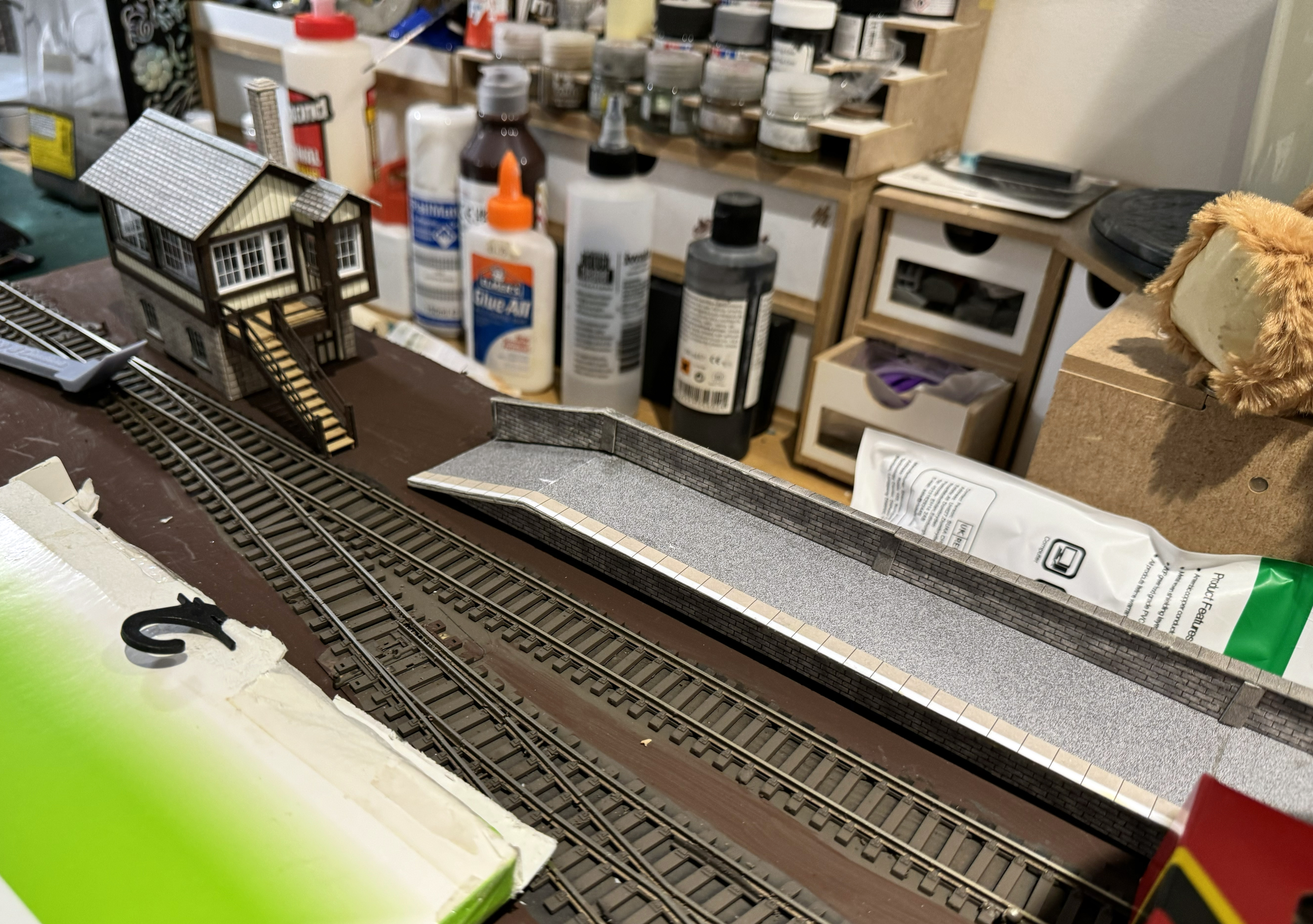
 Now we have the baseboards down and the track spray painted (Railmatch Sleeper Grime) I can get on with building the station. I am using Metcalfe platforms and a laser cut station (can't remember the make). Now that I have the platforms, I have found that the station was too deep to fit so I have had to cut of the back half of the building so that it will sit in half relief against the background (more on that later).

The station building has now been hacked to fit leaving the back open. And you can see, the lights of the cabinet behind make it look as though it has lights fitted. I started to make that really so yesterday but my 5V power supply wasn't working so I have ordered a 5V "Walwart" - as the Americans call them. I have mocked up some furniture for the inside and will put a 3mm LED in each of the three rooms. I am not really impressed with my attempts at the platforms but it's the best that I can do for now and I want to get something down before I start to lay the ballast. Anyway, here is what I have.


The three Hornby boxes contain Mk 1 coaches - 2 x Brake 2nd and a 2nd. They are there to get the platform length right. These will become part of the holiday train that will be pulled by my Accurascale Manor.  I got these off eBay for around £16 each so they were bargains. At the Warley show, I bought three sets of coach lighting but I can't get the roofs off so I am going to use the lighting sets on the GWR Collet coaches and the Auto coach instead. It's a pity as I wanted to put passengers into the coaches but hey ho!

Levers

Here is a photo that I took at the Warley show of "Long Melford". Long Melford is owned by Nigel who lives locally. The railway is supported by both Brett from Orwell Model Railways and Kevin from Coastal DCC. What struck me was how good the signal lever panel looked so I decided to see if I could do something similar although I only have 8 points. As good as my Digitrax system is, it is a bit of a faff to switch the points on the hand controller so a set of levers would resolve that problem.

I had a quick word with the wife and then popped into Coastal DCC to pick up one of the DCC Concepts Cobalt-S levers. After checking with Kevin that it was easy to set up, I found that just three wires from the lever to one of the Cobalt IP Digital  point moters had it going in no time. What was worrying was that I had to remove the "Do Not Use" sticker on the motor warning about plugging the power into that end. I have done this in the past (before they put the stickers on) and the point motors DO NOT LIKE IT!

Anyway, three wires connected and everything worked with the point changing as required.


Further discussions with my wife resulted in me being allocated £106 to buy a box of 6 levers and a pack of the brass numbers to label them up. Coastal and DCC Concepts were both out of stock but I found a shop called House of Hobbies in Ormskirk that said they had stock. Hmmm. 9 days after placing the order I haven't received anything other than the initial confirmation. Also, no answers to 2 e-mails and the phone doesn't get answered. I have put in a report to Paypal so we shall see what happens. I am glad that I used Paypal for this although I tend to when first using a new supplier.

This hobby is expensive. Not only did the levers cost £106 but I have decided that I should put them in a box and connect using DCC Concepts ESP wireless connections. This comprises transmitter boards in the box and a receiver under the baseboard. Each transmitter has three connections, so I will need three of these. The receiver converts the signals from these transmitters into DCC commands and uses a connection to the railway DCC bus to send the appropriate instructions for the point movements. However, this is another £100 or so pounds. Good fun, what! Mind you, without these, I would have needed 21 wires from the box to the layout with three of these 21 going to each point so using the ESP system is much easier. I had to convince SWMBO though.

If the levers come in good time for Xmas, I shall get on with that. Otherwise, I will finish off the station, lighting and placing so that I can get on with the ballasting.

Thursday, 9 November 2023

Running in and new fiddle yard

 I bought one of the new Rapid GWR/BR 15XX shunters from Rails of Sheffield. When it arrived it ran but when I set up a circle of track to run it in, it wouldn't go. An exchange of e-mails with Rails and they agreed to take it back. They even sent me a prepaid label. After a week or so, a parcel arrived and I had the loco back in full working order. Hence the next step was to run it in. 

I bought the circle of track from a trader at the Milton Keynes show - at a cost of £40 - because I had hunted high and low for my rolling road but couldn't find it any where. When setting up a drawer unit that my wife gave me to store my railway stuff - lo and behold - there was the rolling road but pushed right to the back of the drawer. I sold the circle of track to Rails in a bunch of stuff that I no longer needed. 

Here is the 15XX on the rolling road being run in. It is a lovely little loco. The Walchaerts valve gear is especially nice. Note the firebox glow.


Secondly, I have built the fiddle yard. This is a two track storage yard fed by a single point.


This sits on my desk and connects to the main board just using Peco rail joiners. At the moment, the power comes in from the joiners. Next plan is to provide a power feed from the DCC bus on the main board.  Here is all the wiring and the point motor. Note that I use Wago connectors throughout the layout.


My next video will cover the unboxing and running in of my new Accurascale GWR/BR Manor 4-6-0 loco. That's going to be a great addition to the fleet.


Monday, 6 November 2023

A new foam core baseboard works


 So, we have torn down the wooden baseboard as it was totally impractical due to the weight of it all. Even with my wife's help, I couldn't manoeuvre it around with any ease. Now it has gone, I bought a pack of black A1 sheets of 5mm foam core. Black is much stronger than the white. This went together really well and I now have all the track relaid and wired up. Unlike the wooden one, where there were issues with point motors, there are no issues with this version so I can get on and build the fiddle yard.


One of the big changes is that I have got rid of the Cobalt Analog motors and some SwitchPilot accessory decoders as there is much more wiring. Now,I have all Cobalt Digital ones which only need two DCC and one frog wire.

Saturday, 21 October 2023

Moved on a mile

 I built the layout as described using my usual foam core but - stupidly - I cut a hole in one of the side rails to make space for the Digitrax controller panel. Next thing I knew, the side rail had broken and there was a great dip in the layout surface. 

I was concerned about this and thought that I might make the rails out of wood and thus recover the whole thing. Common sense told me to rebuild and I decided to do it using more common plywood/ 3" x 2" planed pine. I even bought a new chop saw to make sure that I built it nice and straight. Well, first off, it was straight but had a few misfits along the way. You would never believe that I used to make oak furniture for a living!

I have got to the point where the track is down, everything is wired up and testing is taking place. 


The only trouble is that I can't lift the boards up as they are very heavy so testing and fixing wiring problems is very difficult. My wife tries to help but, even between us - we are 76 and 78 -, we have trouble. So... Down it will come again only to be rebuilt once more. This time, I am using black foam core (which is much sturdier than the white) but keeping the wooden outer rails. It is the sheets of plywood that are so heavy so this time it may work. I am also reducing the width a bit from 60cm to 40cm in an effort to make it more manageable.The track plan is being simplified from 11 points down to 7 or 8. I will also buy some more Cobalt Digital motors - which weren't available when I started all this. This will reduce the amount of wiring required.

I have spent a good amount of money on locos. I now have the pannier tank and the small prairie but now I have a Rapido 15XX which I am going to use as a local shunter. The problem is that it doesn't work. I am in conversation with Rails of Sheffield, where I bought it, so together we are trying to fix it. I thought that I had lost my rolling road so bought a loop of Hornby track but I have finally found the rolling road so testing should be easier. I have also bought an Accurascale Manor which has just been released. I have also bought a couple of carmine and cream Mk. 1 coaches to go with it and provide a Saturday holiday service. I do need one more coach but I am waiting for the two to arrive so I can get  a second Brake 2nd to match the one I have bought.

More to see soon.

Thursday, 11 May 2023

 Well, the Kato layout went to Rails of Sheffield as did all my US outline N scale and all of the Marklin/Piko/Roco stuff that I had left. SWMBO agreed to a 1.8m x .35m switching layout which I managed to build a running layout. That was as far as it got because I got fed up with the cost of US outline stuff.


I have packed all that away to await my hobby room coming back and some (hopefully) injection of funds down the line. I really like my local hobby shop which comprise Orwell Model Railways and Coastal DCC. Who can complain when Kevin works 5 minutes away! I decided that I would make everything simple and build a nice little GWR branch terminus using (Oh No not again!) Ashburton as the model. Having moaned about the cost of US stuff, I now had to convince SWMBO that £600 as a budget for a new railway was reasonable! Orwells and Coastal will get as much of my spending as possible.


The board has grown to 1.9x .45m. The track is Peco code 100. All the points are medium radius. The points will be switched using DCC Concepts Cobalt  motors. Unfortunately, when I wanted to buy them, the digital motors were unavailable due to chip shortages so I had to buy the Analog ones. I did get one digital so 5 points will be driven by the Cobalt analog motors through Switch Pilots whilst the last one will be driven off the DCC bus, as usual.


I have decided on a layout. I have bought a 64XX and a 45XX plus some wagons and an Auto-Trailer.  I have some Milk tanks on order so I can service a creamery. This will be fun as these wagons are for Express train use and thus can only be used on fitted freights so they will come in and out on the back of the 64XX and the auto-trailer. Great fun.


I have recovered the base of my board (all built of 5mm foam core). I have extended it to the new size and replaced the surface with new board. The track is down and I am in the process of wiring it up.


Friday, 17 March 2023

We have extra lighting

 Our living room is 40' x 18' but the ceiling lighting is just 6x5w LED (used to be 50w Halogens). This means that the railroad sitting on one corner doesn't get enough light to be able to work easily. Hence, I decided to install some "under cabinet" LED puck lights. Thinking about how to do this without annoying the other half led me to think that I could use her pile of Jigsaws that sit on top of the glass cabinets which are directly behind the railroad. I thought that, if I could make a strong structure out of my stock of 5mm foam core, then I could hold it up by sliding the back part under the jigsaw boxes.

The foam core was cut with channels from my 'v' shaped cutter. This enables me to fold the foam core easily. The result looks like this.


The puck lights look like this.


The lighting set came with four lights. The finished article looks like this. (Sorry about the Captain Kirk photo at an angle. My wife told me off for that - she is the Star  Trek fan.)


It's not perfect but it is the best that I can do, given that we rent. At least, I now have consistent lighting across the board which is brilliant.

Wednesday, 1 March 2023

Uncoupling Saga


I have great difficulty using a skewer to uncouple cars so I decided to try out the Kadee under track uncoupler. Stupidly, I bought the 5 that I thought that I would need before testing them out. Well, I have installed one of them.


As I have laid all of my track, I had to cut away from the underside. The magnet is then stuck to the bottom of the track; the hole below is filled with a square of foam core and then a piece of 2mm cardboard  that is larger all round is glued over that to keep it in place. Sorted, I thought and happily went on to the testing stage.

Well (as my youngest daughter would say) that didn't go too well. It seems that  all couplers are not created equal. They may look like Kadees but Kadee they are most definitely not. I tested some of my cars and only the real Kadees worked. I had a long exchange on Model Railroad Hobbyist about the issue and came to the conclusion that I must convert all of the non-Kadees to the real thing. £62 later and I have now received a pack containing 25 pairs of 148 whisker couplers. I have also ordered some "Grease-em" which is a small tube of graphite dust to blow into the coupler boxes.

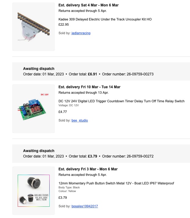
Last week one of my favourite Youtube channels - Chadwick Model Railway - had a video on installing Kadee electric uncouplers which made me wonder. So (again as my daughter would say) I have ordered one set of his recommendations to try out. The complete set comprises a Kadee electric uncoupler, a relay/timer board and a momentary push button as described by Charlie. Here is the eBay order.


I have just received today's post and included in that was the pack of 25 pairs of couplers so I can  at least test out the current under track magnet. More on this to come.


Wednesday, 22 February 2023

The baseboard and track are painted

 Finally, the baseboard is all wired up and sockets fitted for plugging in the ECoS and the 5V DC supply. The staging track has been built and can now be attached to the main board.

First off, the track has been sprayed with "Ammo by MIG" Railway Fast Method paint set. I can't see me using all the colours but the rust worked very well.


I then painted their whole of the baseboard and the staging with some Hobbycraft brown acrylic paint. This has given everything a nice overall colour ready for ballasting.


The staging is attached using a couple of 50mm x10mm magnets. One is set into the staging board and one on the main board. They are strong enough to keep the staging in place but not too strong to affect removal. They also snap into place quite well but I also have a couple of rail joiners to make the final connection.


The site from the staging track connects though a small barrel plug and socket but it isn't really required because the rail joiners make an electrical connection as well.


Lastly, I have built a box to hold all of my current locos and cars. This is made out of the black foam core so is very sturdy. 


Each car has its own compartment. The scruffy bits of foam are made up from an offcut that I bought at the local "foam" shop. These stop the cars from rattling around when I pick up the tray or move it.

There is a photo of each car in the bottom of each compartment so that they can go back where they came from.


Finale

Well that is the current state of play. The track has been cleaned and tested and all of it works as expected. The two locos run  freely and both have sound so they are great fun. I am busy writing some Car Card software. I have decided not to use the software that I wrote for my degree as that was way too complicated for my little switching layout so I am writing some code that mimics the Micromark car cards. I will have more on that once it is capable of operating at its full design capability.

Friday, 10 February 2023

Wiring is all in place

 Having put in a DCC bus and a 5V bus, I now needed to connect up all of the track before I start putting the point motors in. The idea was that I would use some clever suitcase connectors that I got from Amazon that have a socket for a plug that lets a new connection to the bus. However, the suitcases needed squeezing shut and the plugs needed a compression on the wire. Both needed a good set of pliers, which I don't have so I muddled through with a pair of adjustable pliers. 


I carried on and connected all of the track droppers BUT - they didn't work! It seems that I couldn't cramp them tight enough. A combination of the wrong tool and arthritic hands. So, it was a case of going back to the old methods. I have a large collection of some connectors similar to Waco except that they are grey with orange levers (you can see the pass through ones in the image above). I have these as a 2 wire pass through or single channel 3 up to 5 way connectors.  They are a bit messier than the suitcase ones but, at least, I know that they work. After connecting all the track using these, I checked it out to find that a) I had missed a couple of places and b) in two places the wires were reversed! How can you get "black to the back" wrong?

Once I had sorted that out, it was time to go for the point motors. 

Fitting the motors

I have had trouble in the past getting the motors securely fastened to the foam core. Basically, the covering of the foam core is just a sheet of paper either side of the foam interior so there isn't a lot of shear strength in it. I cut out some 2mm plastic card to the footprint of the motor and used UHU glue to attach these at each point location. I had previously drilled pilot holes in the card to match the screw locations on the point motors. Once the glue was fully hardened I located each point through the holes in the board that I had made when laying the points. The screws held the points nice and securely so that all worked.

Now, I have never used the Cobalt Analog motors so I made a bit of a mistake in wiring them up. I assumed that the track voltage feed was all that was necessary along with the frog so I wired the track to 1 and 2 with the frog on 3. Wrong! The track goes to  1 and 2. Then you wire the track to 4 and 5 with the frog in 6. If the loco causes a short when passing over the frog, you reverse 4 and 5.  That sorted I had a railway that was wired.

I bought a couple of Frog Juicers as I was having trouble getting some of the points sorted but eventually the juicers weren't required. 

Adding the Accessory decoders

I use ESU SwitchPilot decoders to run any points that aren't DCC aware. These have to be adapted to operate Cobalt Analog motors as these motors, like Kato points, only require 2 wires and are switched when the plus and negative are reversed. So, we have to add some natty little DCC Concepts gizmos that take the three wire output of the SwitchPilot and convert it to a two wire feed.

As there are 6 points - well 7 actually but two are in a crossover so have the same DCC address - I needed two SwitchPilots. One of these worked and the other didn't. I spent over a day trying to sort this out. I asked questions on the ESU forum and, typically, got no answers. I tried two different SwitchPilots and even replaced them with s TrainTech device and nothing worked.

Finally, I applied a bit of logic and compared the two to see that 1) The lights were on one and not the other and 2) the switch that determines the protocol was on User and not K84. I always thought that User was the right setting but I switched it to the other and all the lights came on.

Finale

Everything worked except one frog feed needed reversing. I have a running layout. Next step is to build a tray to hold all of the cars and locos so that I can put trains together easily on the staging track.

Wednesday, 25 January 2023

First run of Amtrak 737

 While I am waiting to receive the switches for the railroad I thought that I would check out the loco that my friend Dan, in Connecticut, sent me for Christmas a few years ago. I have had it fitted with a sound decoder so it is really a nice piece of kit. Also, I bought a few freight cars on eBay which have now arrived. They were an absolute bargain as the cheapest I can find a car on US web sites is around $19.99 and I paid £15 for these four! I have laid out two yards of track and coupled up the freight cars and of it went.


I think that, considering it has been sitting there for around 3 years, it went very well.

Tuesday, 24 January 2023

Putting in the Wiring Buses

 I am awaiting my LHS (local hobby shop) to get my Peco code 83 switches into stock. They are promised for tomorrow. In the meantime, I have been carrying out a few tasks that can be done without the track.

First off, I have been putting in some wiring for the two busses that I need along the length of the baseboard. These are the DCC bus and a 5V bus for lighting and Arduino use. The DCC bus is laid with 16awg stranded wire whilst the 5V one is 22awg as little power will be going down that. The DCC bus is also twisted. To connect wires together, I use what are called "Lever nut wire connectors" which I get from Amazon.


I have these as shown which are through connectors. I also have a large collection of these for single wire distribution - I have them with 3, 4 and 5 connections. These are convenient for distributing wires around a larger layout. As it is, I use these through connectors as terminations for the two busses. as can be seen in this close up.


The whole underside of the board looks like this now.


The red and black are for the DCC and the white and green are the 5V DC. Once installed, I run them both out to 5mm jack sockets on the side of the layout.


ECoS is my DCC controller. Lastly, I have been laying down some DCC Concepts foam roadbed. I am not sure if this is a mistake laying it before I get the switches but I am laying it down using Copydex, which is rubber based UK carpet glue which should be relatively easy to lift if I need to.


The white extension is the staging yard - off scenic. It is a u-shaped construction out of foam core. I have installed some Neodymium magnets in the end of the staging and the side of the main board and the staging now jumps onto position making it easy for connecting the track between them. As you can see, the staging encroaches onto my computer desk so it has to be moveable.

As I mentioned, I have been promised the switches by Wednesday (tomorrow)  but if they don't come, I will have to think about buying over the internet, which I am reluctant to do. What is happening on the internet is my selling of all my N Scale and unwanted Märkin/Roco/Piko European stock. I have been given some good prices by Rails of Sheffield. So far I have gathered over £250. Although, it doesn't seem like much for each item, eBay was producing worse prices and I need the capital to invest (!!) in some HO stuff. I need a collection of freight cars, at least one more loco (see below) and some structure kits.

The loco that I have is a circa 1942 EMD SW1 ex-NYC that is still in use by Amtrak in Sacramento. There are two arguments against using this. Firstly, I don't really want to model the present day as all the cars would be longer and I don't want to repaint the SW1 as it was a present - although I have fitted it out with a decoder and sound - and a limited edition Walthers item!


Friday, 20 January 2023

We build baseboards

 I have mentioned on many occasions that I make my baseboards out of 5mm foam core. Well, this time is no different, except that I videoed the whole process. I got my usual four sheets of white A1 foam core from Hobbycraft for £10. I then went to my local art gallery/art supplies shop to get a couple of sheets of black foam core. I like this for the basics of the boards as it is much denser than the white and is very much tougher. The only issue is that the art gallery wanted £12.50 per sheet! I did ask how much their white was and the answer was £8.50 - a sheet! I will continue to go to Hobbycraft where their service is great and they know me by name.

OK, so I had all the board that I needed. Then I had to make sure that I had a plentiful supply of hot glue sticks and 2" double sided tape. To outline the process, I cut the white into 3" strips along with a few black one. The top of the boards and the outside of the supporting bars will be black and the rest will be white. When laminated using three sheets and the double sided tape, the resulting girders are very strong. Anyway, I have created a stop frame video of the process. I am sorry that the beginning is dark but I was still getting to understand the process. My nice Olympus mirrorless camera takes up to 999 frames  at your choice of delay and when finished melds them all together into a video - very clever.


Here is the baseboard in position. I have used the legs from the previous layout.


Here is the view from the left hand side where you can see the white extension for the staging.


I have printed out the Anyrail layout in full size and run along the centre of all of the rails with a pounce wheel.  Following that I am outlining them using a white marker. Here are the pounce wheel and the marker.


and here is the board with some of the track centres highlighted.


Next up, I have some DCC Concepts trackbed to go down and, then, when the LHS gets their act together and gets some switches in stock, I will lay the track. As I am waiting for the switches, I will probably put the DCC bus and a 5v bus (for structure lighting) under the board ready.