Monday 10 August 2015

Sorting out the point display panel

As I have mentioned, I have a problem with arthritis which means that I cannot stand and work on the railroad if it is at certain heights. One of these heights happens to match the worktop in the hobby room. The construction of the railroad is intended to be as lightweight as possible so that I can move the individual boards into the living room so that I can work sitting down at the dining table.

The railroad is designed to be operated on the hobby room worktop with me sitting alongside. However, I cannot see how the points are set when sitting down.


Part of the reason for me getting the Cobalt switch machines was to enable an easy way of indicating the routes. The secondary feed from each machine was to be used to drive a couple of LEDs. as described in the Cobalt documentation. I realised that I could make the display simpler if I used a bi-coloured LED rather than individual red and green LEDs. However, I have had experience before in soldering up complex layouts before and there is a great scope for shorts, especially when using D-Sub plugs and sockets as the connections are extremely close together. This meant that I would need to be very careful in the construction of the panel if I wanted this to be in any way robust in a layout that would be taken down and erected with regularity. I, also, wanted to be able to change the wiring very simply. The reason behind this was that the polarity of the points was different depending on which way the frog was set. Rather than have to work all this out, I decided to put everything through a breadboard. Firstly, this would alleviate much of the comoplex wiring and make it simple to reconfigure the LED connections.

The best way to manage the wiring was to make all of the connecting wires to a similar specification to the jumper wires that are used on breadboards. I have some tinned copper wire and lots of heat shrink. This is what each of the LEDs looked like once I had wired them up.


As you can see, all of the connections to the LED have been sealed within heatshrink. Also, I have soldered a small amount of tinned copper wire to the end of each lean (again with heatshrink around) to make an effective plug to go into the breadboard. Once all of the LEDs were finished, I was able to hook everything together. Each LED has one outer leg fed from one side of the DCC bus and the other leg to the opposite side of the bus. The centre pin is connected, via a 1k resistor, to the frog feed of the Cobalt machine. These connections are very simple with the breadboard.

I was a bit hesitant about powering everything up as these things normally don't work first off and I didn't relish searching for the one dry joint! However, I needn't have worried. Putting the power in resulted in all of the switch machines carrying out their self centering action with every LED reacting to the changes. Finally, I made sure that I had each LED labelled up for its correct point.

I had already made a panel out of a sheet of printer paper that I had laminated and fitted to some foam core board with 2mm holes in the foam to accept each LED. However, I had punched holes in the paper. I realised, after reading on MRH about another LED panel, that the LEDs would shine through the white paper. This would make it much neater. Anyway, here is the final result.


I can now sit on my moveable office chair, control the locos and the points from my iPad (using WiThrottle and JMRI) and see the routes as currently set - all without standing up.


As you can see, I need to reconfigure some of the LEDs to match the point orientation. Then the LEDs will be the same as the WiThrottle indicators.


Tuesday 28 July 2015

So that I can finish the track, I need to lay some scenery down

One of the features of the track layout is the sunken coal drops along the front. I have a Walthers Cornerstone National Fuel Depot kit.


As you can see, this comes with a berm leading up to some coal drops. I did plan to use this on my previous layout as I wasn't in a position to cut down into that. I was going to use it on this layout but a comment on the blog suggested that dropping the ground level would make it more interesting.

The good thing about foam board is that you can just cut away. So long as there is some adequate bracing in then everything stays nice and strong. So I cut away. This is where I got to.


I have cut away the base, built the trestle and the fuel tanks and got everything into place. I then gave all of the groundwork a covering of Sculptamold. Later this evening, I gave the fuel tanks a coat of Vallejo Aluminium, the wet and dry paper laid as a road a coat of german field grey and then used one of my airbrushes to spray a coat of brown all over the area.


Obviously, the wooden trestle and the fuel tanks won't stay like this and I haven't even started on the distribution building.I have lots of weathering pastels and washes to make it look as though it has been handling coal for years! The fuel depot will be used as a refuelling point for the SW7 as well.

Monday 27 July 2015

Fitting Cobalt Point Motors - that was fun!

It took a lot of effort and time to get the point motors working. I completely misunderstood the way that these motors work. I got the switching working first time but getting the frog polarity sorted took a good deal of time. It all seemed very simple. I had the main power bus laid by the two stripes of copper tape laid earlier. As I had used red and black wires for the track power, I decided to use orange and blue to connect up the power to the motors.

I had made a template to help lay the points to get the  slot for the  motor fulcrum bar and for the hole to accept the wire for the frog polarity in the right places. I also made a template to fit each motor to the underside of the baseboard. Each motor was fitted using the supplied double sided pad. I did install the four mounting screws as well and they held quite well in the foam board. I was concerned that the motors may skew under whatever force was applied but, in fact, there was no pressure on the motor at all once firmly in place. The fulcrum bars were trimmed down to below rail level using a cut off disc in my Dremel. Lastly, I carefully ensured that the orange and blue wires were all installed with the same polarity.

It is very simple to configure up the motors with the correct DCC IDs. On each motor there is a small switch. Set it to the program position. Using the handset, you then send an accessory command to the chosen address. DCC Concepts recommend that you do this twice but I found that once works. Set the switch back to the run position and it is all done. I quickly set my points up using just 1 to 7 across the two boards.

I put the two baseboards together, connected the two using 9 way D Sub Connectors. It was then that I got a short across the tracks. It turned out that I had crossed the connection of one connector to its bus. How I put red to black and black to red defeats me! After sorting this out, I connected the NCE Power Cab to the bus. As I hadn't yet received my new Broadway SW7, I used my B&M RS3 as a test loco.

On connecting the NCE unit, all of the point motors carried out their self centering operation. On testing each one, they all operated as expected. I did have to adjust the slider on the fulcrum bar of a couple of the motors to ensure that the points actually closed with sufficient force to keep them in place. I then tried to run the loco and immediately got a short as it met the first frog. Two days of frustration followed. I put a posting up on RMWeb (one of the UK's big model railway forums) and got lots of ideas but nothing helped.

I built a test bed to have a clear idea what was going on but that worked correctly, so I was totally bemused. I then tried the loco through each point and found that it would go through some of them but not others. After a lot of head scratching and loss of sleep, I finally realised what was going on. When testing with a continuity tester, I found the following situation on the good points.
where the red line shows no short and the green indicates a short. This is what you expect and means that the frog is powered with the correct polarity. However, on some of the points, I found the following situation:
On these points, the frog was set to the wrong polarity. I had a bit of an epiphany when I saw that, from one perspective, all of the good points were in a facing position and all of the bad ones were trailing. Slowly, I realised that I had been thinking that the Cobalts were like the old Frog Juicers that I was using previously but they are not! The Frog Juicers start up in a random situation - so the polarity of the frog is indeterminate. This doesn't matter because, when the loco hits the point, the Juicer sorts out the polarity and puts it right if need be. The Cobalts, on the other hand, are switches that conform to the way that the logic says they should be. So, if a right hand point is set to the straight road on start up, the frog will be set the same way. This is based on the polarity of the power coming in, in the sense of which side of the bus is set to which connection. My realisation told me that a trailing point would see the polarity as opposite to a facing point and, thus, would power the frog with the opposite polarity. hence my shorts! This was quickly tested by switching the orange and blue wires on the trailing points to the opposite way to the facing and everything worked. It was pointed out, when I reported this on RMWeb, that this would also need to be done if the motor was fitted in the opposite way on a point - say because of a baseboard element being in the way. I have to say that I would have thought that this might have been indicated in the documentation but I can find no mention of the issue.


Friday 17 July 2015

S & NE - the track is down and the wiring is done.

I have put together the two main boards. As mentioned, these are made of 5mm foam board and are extremely light. Each board weighs just 750 grams (1lb 12oz) but they are very well braced and have self levellers to get them straight and level on the worktop where I am going to run them.


There is one more track to lay. That is going out along the front towards the right end. This will be the track that goes out over the coal drops but I thought I would leave that complication until I had everything else done.


Here you can see the underneath in all of its glory. You can see the main DCC bus running along the length of the two boards. The electric feeds are carried from one board to the other by a 9 way D-Sub connecter (of old VGA fame). This has enough connectors for me to run the frog feeds from one board to the other to provide an LED display of switch settings. The little bumps on the bus are where I have cut through the copper because there is a switch at that point and I need to cut a hole for the point motor wire!

The above in an annotated close up image of a section of the board showing all the salient features.  The little blobs of hot glue that you can see are where I have fixed the track pins into place. I lay the track on double sided tape but it needs some extra help so I put track pins through and then hot glue to hold them down. Once the track as been ballasted, all of the pins with their attendant hot glue tips can be removed.

My last couple of images show how the two boards are held together. remember that these two boards weigh only 1.5kg in total so are not subject to much kinetic energy if moved so the joins can be held in place quite easily by creating two foam core locks. The first image shows it all in place and the second shows on lock in the halfway out position. (The two boards were not fully in place hence the gap under the rails.)


This might look insubstantial but it works very well.In fact, when I have built some scenery and placed some structures, I can use these self same slots to insert spacers between the two boards for storage (for more please wait until later).

I have checked all of the electrics and, as you can see in the first image, run my B&M RS3 up and down. It had some trouble with shorting frogs but I haven't got to sorting them out yet - this will be managed by the point motors. This weekend I am making my first visit to the Thamesside Modellers which is a North American Model Railroad club some 23 miles from me. I will let you know how I get on. I am expecting to start installing the Cobalt IP point motors on Sunday so more then.


Thursday 9 July 2015

Testing my new Cobalt point motors

The Cobalt switch motors are very flexible. They can operate on DC or DCC, change the polarity of the frog, power LEDs to show the road selected and interface with switches or other devices. I only need  the basic switch operation, the frog switching and the LED management.

As I have never used them before, I thought I would put up a test rig. Here it is with the switch in place. I knocked it together from some scrap foam board so that it was installed in the same environment as the final layout.


The track is held down on double sided carpet tape and alignment is fixed by the use of a few small pins through the ties. On the real layout, everything will be firmed up when the ballast is laid.

OK, so we switch to the underneath now.


This is the Cobalt motor in place. It is held there using the same double sided tape as for the track. In the final installation, of course, I will be using the DCC Concepts supplied double sided pad which is a lot stickier.As you can see, there are two wires (red and black) going to the track. These provide the power for the motor.There is also a resistor installed in the frog polarity control. This is connected to two LED (one reversed vis-a-vis the other) and one leg of each LED is connected to the track feed.

I have set the accessory number for the switch. This is easily done. You just move the little on-board switch to the Set position and use your DCC controller to address the switch - I used Accessory 1 for this test. It gets the command and sets the address. From then, you put the switch back to Run and you are done. I now have a test switch that is operated by my NCE controller and gives me a LED indication of which road is set.

You might notice that both LEDs are white - I don't have any other colours so I have some red and green ones coming. This is going to be fun!

The baseboard is finished - ready for the next step

I have finished making the baseboards. Today, I fitted some adjustable bolts to the corners of each board. I then set the boards up on my work top in the hobby room and got everything at a matching level. Here you can see it in place.


Here is a close up shot of the levelling system. There is one of these on all eight corners.


The next step is to test out my new point motors. I have just purchased 7 of the nice DCC Concepts Cobalt IP Slow Action Digital Point Motors. These are nice units that have a decoder built in. Not only that, but they have a connection to manage the frog polarity plus two extra connections for LED outputs ti show point orientation. Very clever - and all for the price of a Tortoise. I am going to build a small test bed with a single point and two spurs to test out the wiring but also to test out the point motor fitting. As I am using foam board, I have to make good arrangements for the mounting otherwise the motor could, over time, break away. More on that tomorrow.


Monday 29 June 2015

Like Phoenix, the S&NE arises from the (metaphorical) ashes

As I mentioned, I am giving up on building a high level, around the room, layout in favour of a small switching layout that I can construct and run sitting at the dining room table.

Plan A was to design a layout and build it but I am at a loss for a decent track plan. I have decided to build the layout and then design the track in situ.

As usual, I am in acquisitive mode, as always at the start of a new project. I have had to move the timeline up a bit as I wasn't able to source an SW7 at a price that I could afford -remember that I like DCC and sound. I was able to get a Broadway SW1500 for £105.00 ($165) delivered so that has forced me into the late '60s. A new SW7 would have cost me about $200 with shipping to the UK. Amazingly, these items are on sale in the UK but the price I have seen is around $320!

Here is the current plan. Small switching layout with around 6 switches. I am hoping to have them controlled with Cobalt IP Digital point motors. I am looking forward to converting my Switch List program from providing train make up into one that delivers car by car destinations.

Anyway, I have started making the foam board bases. This is where I am at the moment. There are two boards. One is shown partially constructed.


The copper strips down the middle are the two sides of the power bus. Last time I made boards like this, I forgot and had to feed the copper tape over each of the internal support struts! Once, I know thelocations of the switches I will put more supports in so, eventually, both structures will be very strong.

More soon.

Saturday 13 June 2015

Yet another sad day for the Sunset and North Eastern

I have been posting news of the S&NE over the last year and felt that I was finally getting somewhere with a permanent HO layout. If you remember, I had written some software to do the scheduling and was getting on wth the scenery and the structures. However, physically, things have been getting worse - rheumatoid arthritis in the lower back is the issue here. I set the level of the layout to be the same as kitchen units - mainly so that I could get an under the counter freezer in the room. However, this is just the height to give my back its worst possible outing and I am now at the point where I cannot work at the railroad for more than about 10 minutes at a time.
The only way forward it to revert to a much smaller layout that I can put on the dining room table to build and hook up with some staging to run. So, all of the existing stuff has come down. I have, fortunately, recovered all of the code 80 Peco track so I have a good start. I am planning a foam board based pike that will be up to a max of about 4' x 1' 3" to 1' 6" with about 6' of staging hanging off it. 
I thought that Kalmbach had a book available for small switching roads like this but I can't find anything. One of the problems I have found over the years is that I am not very good at track design and, no matter how hard I try, the final layout always has problems that ruin the fun. This last one had just that - some of the spurs were too short and the caboose track was in the wrong place making yard switching quite difficult and not much fun.
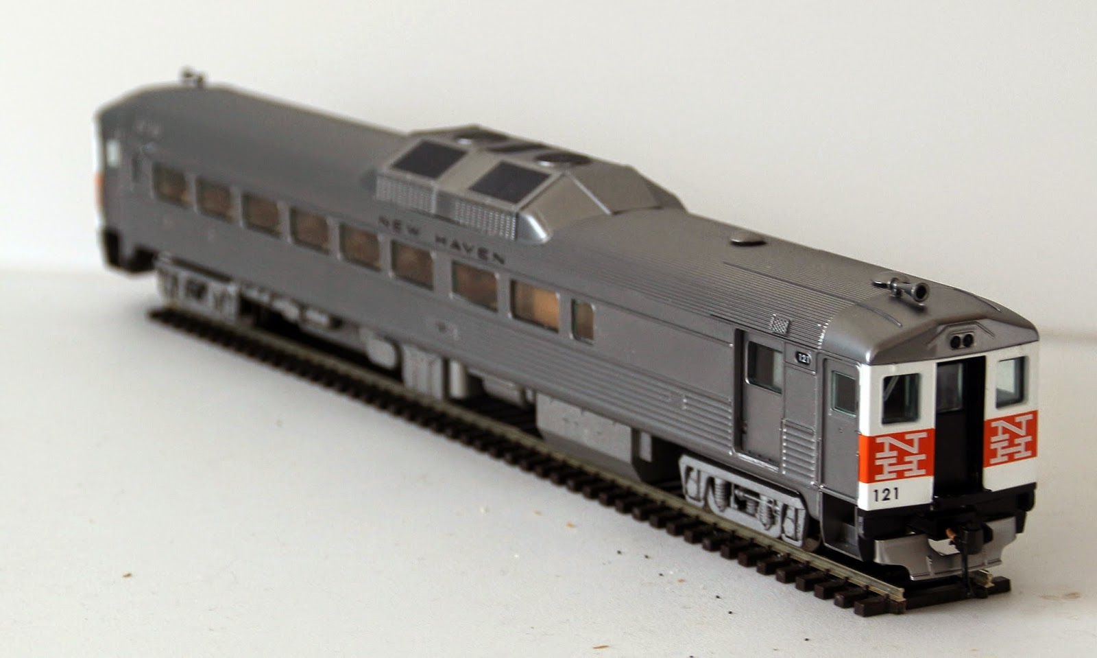
So, how do I go about making sure that what gets built here has  a lot of fun available. I realise that I will have short spurs and a tight runaround. Using John Armstrong's ideas, the givens are just the size of the layout. The druthers are that I can spend 30 minutes or so switching back and forth and that I have a small raised platform somewhere so that I can run my New Haven Budd RDC in and out to get in the way. I have at least 10 yards of track and 13 points so track isn't a limiter. I have three steam locos - 2 moguls and an 0-6-0 switcher but these are probably too big for this. I also have a B&M RS-3 but again size is an issue. I can probably justify a Broadway Limited SW-7 or SW1500 for the switcher. I do like DCC and sound so either of these would fit fine. I have over 20 1950s era freight cars and 3 cabooses.
Right, so how do I go forward - any ideas would be welcome. I am retired so I have all the time in the world - smile.

Wednesday 6 May 2015

More sculptamold goes down

I am getting back onto putting more Sculptamold down so that I can get going on the scenic detailing of the back side of the railroad. Firstly, I had to cope with the tine gap along the window cill. As I can't do anything permanent to the walls (we rent the apartment) everything that I do has to be held separate from the wall, etc. here I had a little problem. There is a very small gap along behind the railroad - no more than 1" at its greatest. It is interesting that the gap gets smaller as it goes along but, on testing, neither the window cill or the railroad baseboard seem to be out! In any case no freight car rolls on the rails when placed so I will stop worrying about it. I found an image of a wooden fence on the internet. I put this into photoshop. I trimmed it and patched it into a long line. I also put some scenery behind the fence but it turned out that very little of that could be seen. Then, using Adobe Illustrator, I placed this on a sheet of paper with as many copies as I could fit and printed it all out. Each line looked like this:


Securing these to some foam board using double side tape gave me a nice background under the cill.


I then cut out a couple of pieces of foam board to match the floor of both the freight house and the station building. The idea was to raise these up so that they were at the right level against the track taking in the height of the foam road bed and to give a flat area to fix them in place when I get to them. I then started to ladle Sculptamold onto the baseboard being very careful when placing it near to the ballast.


Stopping for a while, I got out my plaster bandage (Mod Roc as it is called in the UK) and, using some old newspaper, built up a hill in the right hand corner of the layout.


In the image above, I have started covering the bandage with Sculptamold.

It is all starting to go together. When it is dry, I will paint it to match the rest of the groundwork. I need to make a platform for the passengers (remember that the station building is derelict). I am planning on a simple wooden plank structure which would have been seen as sufficient in the 1950s. I also need to make a tarmac base for the working area of the freight house and then put a small road in that goes off to the left behind some trees. Just to finish, I thought I would show you the derelict station in situ (I have added a Keep Out sign to the door).


Saturday 2 May 2015

Change of heart with the Pine Valley Station Building

If you go back a couple of posts, you will find that I had a story regarding the station building at Sunset. I was trying to build a legend to cover the fact that the building was a little too small for its supposed location at the main station for the railroad. I had a lot of problems with the roof of the structure, mostly because I used a water based glue to fix the shingles rather than the recommended double sided tape. The result was that the roof warped very dramatically. I have finally got it fixed but in the process came up with a better idea. here goes:

Up until the lat 1920s, the Sunset and North Eastern ran a small passenger service across the line from Boston to Hartford. With the Wall Street crash, the passenger traffic all but disappeared and eventually they closed up the station building as they finally decided to stop all coach traffic on the line. That's how it stayed until the birth of the RDC. The New Haven bought some of these and realised that they could have a quicker route to Boston than the current route over their own and the B&M tracks if they got some trackage rights over the S&NE. Suddenly, the S&NE had to make some provision for passengers at Sunset. The station building was, by now, too run down to resurrect so they did the simple thing - the put a platform down and left it to the New Haven to manage ticketing, etc. on the RDCs.

I got this idea from trips I have made on the New Haven. I have a business colleague/friend who lives in Windsor Locks, CT. I have made a few trips into New York with him. The "station" at Windsor Locks is just a car park and a slightly raised platform about 50' long.

Anyway, I am some way into completing the building. It still needs some extra weathering and settling onto its platform and then settling the whole thing into the ground. This is where I am:

Sunset Passenger Station (partly derelict)

I have blocked all the windows up. I am going to put a few warning signs around. It should end up looking quite good, I think.

Saturday 21 March 2015

Progress on Pine Valley Station - and a forgotten memory

I have now completed the walls and the roof. Both have been airbrushed and are ready to be joined. Unfortunately, applying the shingles and painting them has caused the roof to warp fairly severely. I am going to attach some thick plastic card to the underside of the roof and I have glued some tabs to the building. Once put together, the warping should have been alleviated.


I will get some more done today. It seems that my decision to spend one day at a time on each of my projects has fallen at the first fence as I would really like to get this little gem finished!

Whilst clearing out the drawer on my side of the bed (what a treasure trove - two diaries from the 1970s and an old wallet, plus a photo of my whole school from the class of 1960!) I found this:


This is a Lionel Trains themed watch. Back in the 1990s I was involved in the design and selling of bank trading room software. As part of this, I had cause to visit US Bank in Minneapolis. (For those of you that don't know, I live in the UK so this was a great treat). I remember coming out of a bar at 10.30 on the first night there and remarking to my colleague, Steve Anderson, that it was rather cold. I was wearing just a thin jacket at the time. On being told that it was 0 degrees, I thought little of it until I realised that I was thinking centigrade whilst he was thinking fahrenheit! I have to say that I fairly ran back to the hotel. Anyway, on both occasions I dealt directly with the bank's Treasury Manager - a guy called Lars Lidberg. Is it true that all Minnesota residents are Scandinavian by heritage? He was a really nice guy. I mentioned to him that I had been to the Mall of America and that there had been a great model railroad shop in the Mall. About a month after my second visit, a parcel came to me in London. In it was this watch from Lars. What a nice treat and what a nice guy to do this to what was essentially a salesman. I have to add that I used to be a trader myself and in fact had dealt with his bank many times in the past so we did have a lot in common and much to talk about. Here is the watch itself.


As you can see, when going, the train runs around the dial. Wonderful!


Friday 20 March 2015

Let's get some real modelling - Pine Valley Station

Having worked out that I have about 17 things on the go at the moment, a kind soul on the Model Railroad Hobbyist Forum suggested that I allocate a whole week to each of the task. This seems a bit extreme so I have decided to dedicate one whole day to each task. Today is Model Railroading (of course!)

So, I have opened the Carolina Craftsman Kit of Pine Valley Station. There is a slight problem with this choice of kit in that the building is a bit small for the main depot of the S&NE. However, I have a story. The railroad is set in the 1950s. Way back in the 1930s within the Depression era, the railroad was struggling to keep a passenger service going between Hartford and Boston given that there were other routes served by the bigger railroads (the New Haven and the B&M). A quick trip to Springfield from Hartford and then across to Boston on a timetable that covered the whole day made that route the best choice. They closed down the service and for 20 years there was no passenger trains at all. In 1950, the New Haven decided - after consultation with the S&NE - to have a three times a day service in each direction from Hartford to Boston and back using one of their new Budd railcars over the S&NE. As the S&NE had demolished the station at Sunset  they pulled out an old design that they had and quickly erected a new station building. As the service was to be infrequent, they only only built a small station building - not expecting too much traffic.


Well, how am I getting on. It is is a fairly simple kit. Firstly, I put some bracing behind the walls.


Then, using a piece of mirror as a flat base, I stuck the walls together. BTW, I like Deluxe Materials Roket Card Glue for jobs like this. It is very fluid and sticks very quickly. 


The final job, so far, was to spray the provided Tichy windows with Vallejo Mahogany Brown.


That's it for now. This afternoon, I intend to paint the walls and make the base. Watch this space.


Saturday 21 February 2015

The switch list works

I spent a lot of time building a spreadsheet to make a timetable for the layout. Although there is only one station on the layout, it is supposedly at the centre of a feeder line between Hartford CT and Boston MA. The vital bits of the spreadsheet look like this:


BM2-101 BM2-103 SNE2-1 SNE2-2 NH1-67 NH1-69 NH1-71
Hartford 10:10 06:04 02:00 05:00 06:00 10:00 14:00
Tolland 11:46 07:40 05:07 08:07 06:52 10:52 14:52
Stafford 12:19 08:13 06:30 09:30 07:11 11:11 15:11
Southbridge 13:14 09:08 08:30 11:30 07:42 11:42 15:42
Charlton 13:42 09:36 09:45 12:45 07:58 11:58 15:58
Auburn 14:19 10:13 11:15 14:15 08:19 12:19 16:19
Sunset 14:42 10:36 12:22 15:22 08:33 12:33 16:33


SNE3-1 SNE3-2


Sunset 14:42 10:36 06:00 13:00 08:35 12:35 16:35
Westborough 15:33 11:27 07:52 14:52 09:04 13:04 17:04
Framingham 16:33 12:27 10:00 17:00 09:37 13:37 17:37
Wellesley 17:05 12:59 11:22 18:22 09:56 13:56 17:56
Newton 18:14 14:08 13:45 20:45 10:34 14:34 18:34
Allston 18:33 14:27 14:45 21:45 10:45 14:45 18:45
Boston 18:56 14:50 15:52 22:52 10:59 14:59 18:59

BM1-102 BM1-104 SNE4-1 SNE4-2 NH1-68 NH1-70 NH1-72
Boston 03:00 07:15 02:00 06:00 08:00 12:00 16:00
Allston 03:23 07:38 03:07 07:07 08:14 12:14 16:14
Newton 03:41 07:56 04:07 08:07 08:25 12:25 16:25
Wellesley 04:50 09:05 06:30 10:30 09:03 13:03 17:03
Framingham 05:23 09:38 07:52 11:52 09:22 13:22 17:22
Westborough 06:23 10:38 10:00 14:00 09:55 13:55 17:55
Sunset 07:13 11:28 11:52 15:52 10:24 14:24 18:24


SNE1-1 SNE1-2


Sunset 07:13 11:28 10:00 14:00 10:26 14:26 18:26
Auburn 07:36 11:51 11:07 15:07 10:40 14:40 18:40
Charlton 08:13 12:28 12:37 16:37 11:01 15:01 19:01
Southbridge 08:41 12:56 13:52 17:52 11:17 15:17 19:17
Stafford 09:36 13:51 15:52 19:52 11:48 15:48 19:48
Tolland 10:09 14:24 17:15 21:15 12:07 16:07 20:07
Hartford 11:46 16:01 20:22 00:22 12:59 16:59 20:59

The above matrix shows all of the possible trains that run in a single day. This took a lot of manipulating to ensure that locos, cabooses and RDCs were always in the right place to enable the next required train to run. The timings were calculated as follows:

Type Avge Speed Max Speed Stop Time
RDC 25 45 2
Through Freight 13 25 0
Way Freight 8 25 30

This lets me calculate the times between stations on the route and thus get the appropriate times for action through Sunset. I have to admit that I haven't gone the next step and ensured that there aren't any problems with passing of trains between stations. As the rest of the railroad doesn't exist, it would have been a lot of work for nothing. Mind you, the plan for the layout includes me building a second station later when I complete the full circuit of the room. I will probably have to rework the timetable at that point.

Anyway, I got all the information sorted and put it into the CSV that defines the trains. This CSV looks like this:

Name Route Capacity Stopping HasCaboose SingleUnit Times RunOrder
SNE Way Freight #1 SNE1 5 y y n 10.00:20.22 4
SNE Way Freight #2 SNE1 5 y y n 14.00:00.22 12
SNE Way Freight #1 SNE2 5 y y n 02.00:12.22 9
SNE Way Freight #2 SNE2 5 y y n 05.00:15.22 16
SNE Way Freight #1 SNE3 5 y y n 06.00:15.52 1
SNE Way Freight #2 SNE3 5 y y n 13.00:22.52 11
SNE Way Freight #1 SNE4 5 y y n 02.00:11.52 8
SNE Way Freight #4 SNE4 5 y y n 06.00:15.52 15
BM Thru Fr. #102 BM1 7 n y n 03.00:07.13:11.46 2
BM Thru Fr.  #101 BM2 7 n y n 10.10:14.42:18.56 14
BM Thru Fr. #104 BM1 7 n y n 07.15:11.28:16.01 7
BM Thru Fr. #103 BM2 7 n y n 06.04:10.36:14.50 6
NH Commuter #67 NH1 1 y n y 06.00:08.35:10.59 3
NH Commuter #68 NH2 1 y n y 08.00:10.26:12.59 5
NH Commuter #69 NH1 1 y n y 10.00:12.35:14.59 10
NH Commuter #70 NH2 1 y n y 12:00:14.26:16.59 13
NH Commuter #71 NH1 1 y n y 14.00:16.35:18.59 17
NH Commuter #72 NH2 1 y n y 16.00:18.26:20.59 18

From this data, the software can work out each train in the correct order. I ran the whole thing through, yesterday, and it worked fine. It might look a bit strange when you see the start times - these don't correspond with the running order - but you must remember that the aim is to get a train through Sunset so start times from Hartford or Boston are irrelevant and only the Sunset time matters.

So far, there is only one small problem. It seems that the software delivered a Reefer to the Lumber Yard! I am going to run the software for a few logical days before I try looking for the problem. I have looked at the code but I couldn't see why it should have happened so maybe it was a carry over from all of the test runs. Let's wait and see. 

What was good was that when I did a full 18 train run, the system reverted back to train number 1 and all of the locos and cabooses were in the correct places to start the next day. We shall see whether it actually keeps to track capacities.

For those of a technical bent, the software is written in Instantiations VisualAge Smalltalk 8.6.1 with all of the web design being built using the Seaside add-on. I have been writing software in Smalltalk for 24 years now and cannot recommend it too highly. If you want to build bug free software quickly and efficiently, Smalltalk is the way to go. For more on Instantiations VA Smalltalk, check out their  Web Page and for more information on Smalltalk, check out Wikipedia. More information about Seaside is available here