Well, having made the baseboards, I got going on building the railway itself. Firstly, I will talk about the layout. The main station is taken from the layout that I started building in the flat. I liked the layout and had covered its use on the computer so it made planning a bit easier. The track then runs round the back of the garage onto the other side which is a fiddle yard of one track off the main. The main then continues round over the bridge (which is removable) back onto the station board again. Where there was a little head shunt at the end of the platforms on the old layout is now a connection to the branch station. This track crosses over the board at the back of the garage but slopes down about 1 1/2 inches in to the branch station. The branch station is set on a baseboard that is below the fiddle yard - to give a separation from that. The branch station will have a runaround and a single track into the goods yard. The traffic will be mostly coal but with the occasional general goods and cattle going out.
Here is a sketch of the plan. I will put up a proper Anyrail image later when the track plan is really sorted as I only have the main loop set up on Anyrail at the moment.
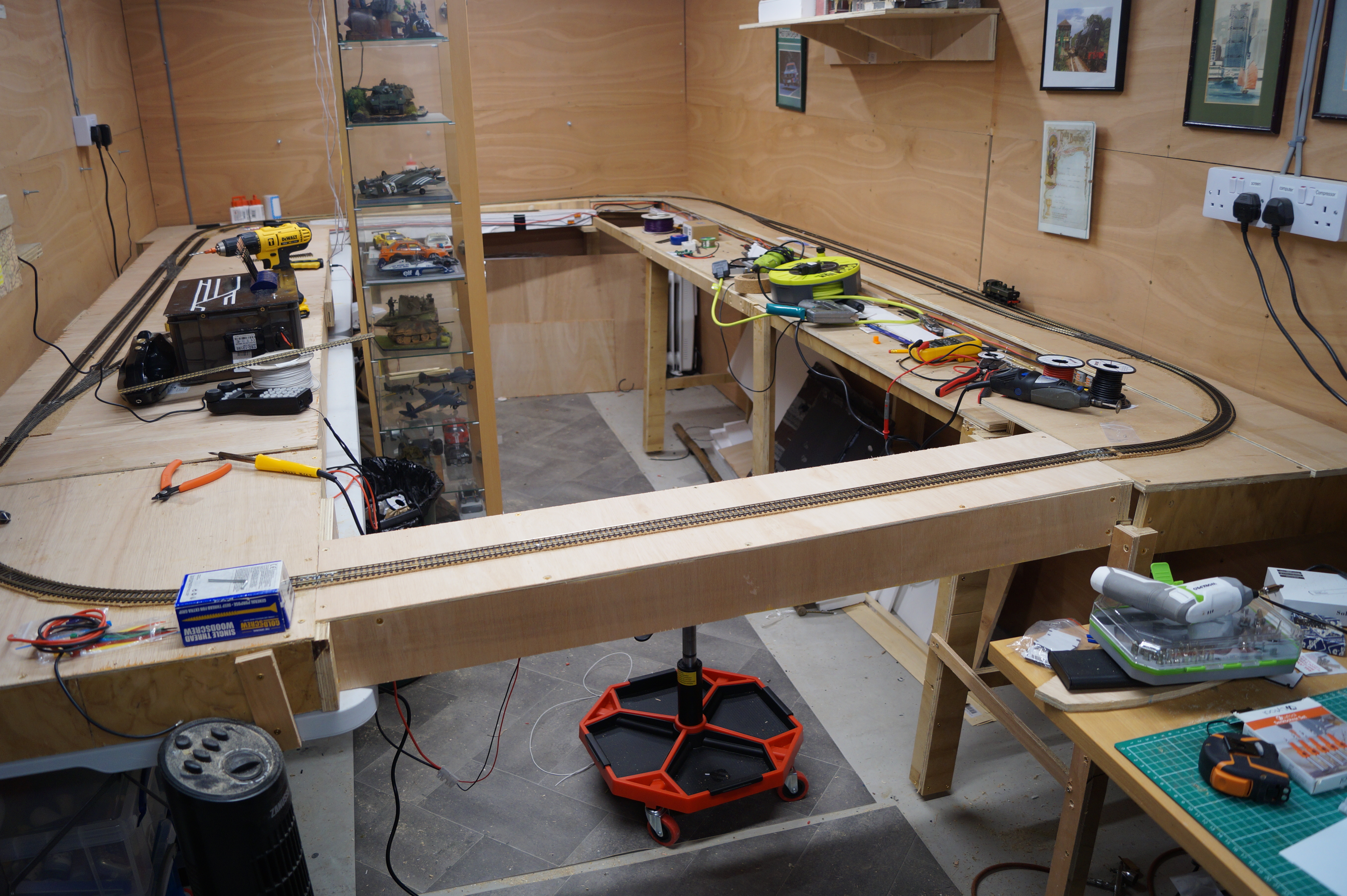
Here is a shot of the undernea th of the main board which gives a good indication as to how the electrics/electronics are going to be sorted.
We have the main track bus - the thick red and black wires which are connecting all the areas of the track to ensure full connectivity for the DCC signal. The point motors are all DCC Concepts IP Digital and are currently wired incorrectly in the photo. I assumed that I could connects the motors with the black and red in the first two sockets and the frog in the third. Wrong! More a bit later.
I continued all around the layout with the main track bus. Doing something that I couldn't do before, I put in an Accessory bus to connect the point motors to the DCC Concepts ESP® Wireless DCC Receiver Unit. I have a nice control box using DCC Concepts point levers that is connected wirelessly to this unit.
I got all the track wired up along with the point motors but nothing worked!
As shown in the image below, there is a right and a wrong way to connect the IP Digital point motor to the main buses when you have an accessory bus as well as a track bus. Basically, you need to connect the accessory bus wires to sockets 1 & 2. This provides the digital instructions from the DCC system to the point motor. Then you connect the track bus to sockets 4 and 5 so that the frog wire, that goes into socket 6, can get the correct feed when a short occurs as a loco runs through the point.
I, stupidly, thought that just the track bus to 1 & 2 and then the frog wire to 3 would work but that was wrong. Nothing worked. I thought for a couple of days and worked it out.
After I had got all this working, I had to finish laying the track for the whole loop line. It was only the two tracks from the left hand point on the "fiddle yard" through the right hand point and the last connection to the removable bridge. That done, I started to test it all to find that the last point - the right hand one on the "fiddle yard" - didn't work. I spent two days trying to work out why the one point was a failure. Finally, on tracing the wires, I found that the white lead from the point to the accessory bus had never been connected! In fact, it had never even been stripped. It was as it was after being cut off the reel! Once, I stripped and connected the wire to the appropriate bus it all worked.
Well, that is where I am now. I have a single track loop all around the garage with a double track through line fiddle yard. Exactly what I wanted so I can now start to, firstly run trains and, secondly start to lay the main station.
If you look at the back of the room, you can see a glass display case. This has all of my scale plastic models that I have built over the last few years. It is destined to be placed right at the back of the room in front of the two tracks that link both sides of the main track. However, I have been thinking about this and now plan to purchase 5 40cm wide glass fronted cabinets to fit on that back wall. Then, we can get rid of the display cabinet and have the floor clear.