Wednesday 28 August 2013

Point operation test bed

Those of you that have been following my progress on my new OO9 layout here:
http://gentlemr.blogspot.co.uk/2013/08/starting-build.html

know that I am building it on a B&Q door covered in 5mm foam board.

The issues that I now have involve fixing the track and operating the points. My intention is to use double side tape ( using the trade type I get from my local Toolstation ) and to use tube-and-wire for the main station points.

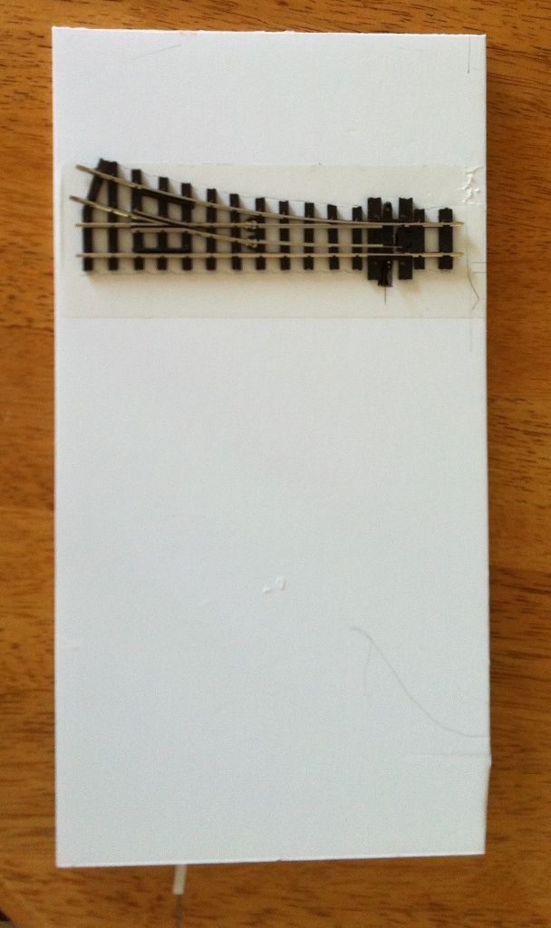
To make sure that everything was going to work, I made a small prototype. Firstly, here is the top side with the point fixed using the tape.


The next photo shows the tube fixed down with hot glue to the foam board and the wire inserted. The tube and the wire came from our "local" model aircraft shop - A1 Models in Colchester since Galaxy Models closed in Ipswich!


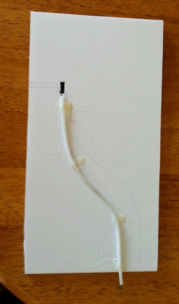
The tube is very stiff so I had to immerse it in boiling water to get it to bend. The wire is very tough and I had a bit of a job cutting it - I only had my sprue cutter available at the time, which is designed for cutting plastic parts of their sprues - not the most heavy weight tool.

It all works very well. I am now going to leave it overnight to see how the glue fares. I will also give the point as many changes as I can as the day goes along to see if that makes anything come adrift.

I will report on progress.

Monday 26 August 2013

Starting the build


I have decided to go with the plan that I ended up with last week.

This is what  I have done.

I am building the layout on a 6' x 18" shelf. The main base is a B&Q panel door. I have cut it to size to fit the space I have and carved out the docks I wanted. I have also cut it around the cabinet which abuts it on the left hand end. Then I have cut out a foam board primary base on which I am going to lay the track. What you see in this photo is the foam board cut to fit and with the layout plan drawn out on it. 

The layout is very straight against the front of the board but what the drawing does is give me the space available around the track and checks whether everything is going to fit. When I actually lay the track, I will relay everything so that nothing is parallel to the board edges and all the angles become smooth curves. The foam board gets cut along the track to enable me to lay out the gradients so what you see is like a drawing rather then the real thing.

The foam board is going to be reinforced underneath to stop it warping. This will be done with more foam board that will be hot glued into place as a complex framework. 

I intend that the points in the main station (to the front) will be operated by wire whilst the points on the raised slate quarry at the back will be operated by point motors fitted with DCC decoders.

Here is the board fully laid out.

wblog041_zps3151031b.jpg?t=1377546540

This is where it will be living one it is all sorted out.
wblog042_zpsbbe50054.jpg?t=1377546540


Monday 19 August 2013

Bhynsell gets a plan


I have tweaked the plan that I came up with before. I have expanded the width of the board just a little and enlarged the fiddle yard area so that I can get a better radius on the main curve. I was playing around with the idea of getting a round-roundy bit  around the back but it was all getting a bit tight and a bit complicated. I don't want to give up on this because it is a complex project.

Right,so this is what I came up with.

plan030_zps1b28c4c1.jpg
Basically, it is a small terminus that connects to the outside world via the fiddle yard. It also has a small branch running off to the back to a slate quarry. Behind the station and behind the slate quarry will be vertical slate walls. The quarry is planned to be just 2" above the baseboard level. I have included a little siding in the quarry for other supplies to be taken. There will be room for two trains of 5 slate wagons (the PD 3 tonners). These will be taken up and down the hill without a brake van but when shifted out on the main line(?) they will be combined with other goods wagons and a guards van. I am also having a two coach passenger train to go in and out of the FY on an occasional basis. There will also be a workers morning and afternoon train to and from the quarry.

In addition, there is a quayside where fishing boats dock. The track there will be sunk into the cobble sets to make a roadside (a bit like Poole Harbour but not so big - grin).

I know that the gradient is a bit steep but my Chris Ward loco is well weighted and I have tested it with five slate wagons up a 1:24 - 4%-ish slope and it works for me. I will double test when laying the track so I don't get caught out.


I have been reading too many Iain Rice books as I have had a go at colouring up the plan with watercolours to get a better feel for what it will look like.

plan029_zpsa9b8b14a.jpg


The run-around at the quarry is purposely "wonky". Having started a discussion about turntables, I decided that I like them so I have included a 90mm one. Whether this is the nice Kitwood Hill one or one that I make myself, I am not sure. I think it depends on how much the Kitwood Hill kit is as no price is mentioned on the web site.


Friday 16 August 2013

My little Prince has sound

This is an experiment. As you will have seen in a previous post, I have put a decoder into my little CW Prince loco and it works fine. I have now got hold of a Digitrax SDH164D sound decoder from my good friend Kevin at Coastal DCC. He has loaded it with a custom sound file (the standard steam sound is for a US switcher). The one he has loaded up is

Loco Model BR#5526 "Light Prarie Tank" 2-6-2 engine Scheme

I know that this isn't correct but it is the closest I could get. I have set up the sound decoder and the loco as a consist. This is purely for test purposes at the moment but if it works out I will be putting the sound decoder and the speaker in a box up in the light arch so we should get a non-directional sound. Given my little Prince, this is probably as good as it gets!

I think that I might have to put a dummy motor load onto the sound chip to get it to work completely correctly but I will speak to my DCC guru abut that. I know that, without a motor load, it is not possible to read back any CV. More on this when I know myself.

Let me know what you think. Please remember that I have had this sound chip about 10 minutes so I have yet to get fully to grips with it.

Tuesday 13 August 2013

Chris Ward Loco and wagons

As mentioned in the previous post, I have built a little Chris Ward loco and 5 Parkside Dundas 3 ton slate wagons. Here are some photos. Now I have a close up photo of the loco, I can see that I didn't do too good a job of smoothing out the little ridges that come with 3D printing. Never mind, I can always strip the paint off and do a better job. Mind you, I might leave that for now whilst I get the layout on the move. Note that the base board is an internal door cut up. This gives me a very light board that is structurally strong. More shots as I move along.


You can click on each photo to see a larger version.

BTW, the loco will be named for my great wife - Valerie (who hates being called Val but that is all there is room for). I have ordered a set of brass name plates but they may take some time to come.

The wagons have been coupled by fitting dumb buffers to each end, fixing a wire across those at one end and the fitting a static hook on the other end. I have used a spare wire from the Chris Ward tender to attach them to the loco. I do have some Greenwich couplers coming so I will see how they go.

Moving on with OO9

I am having a great time with this OO9 malarkey.  I bought a couple of yards of Peco crazy track, a Chris Ward "Prince" loco kit and a pack of 5 Parkside Dundas 3 ton slate wagons from the OO9 Society. The loco needed some flattening out as the 3D printing process leaves little ridges. The little wagons were intricate but I managed to get them together. I filled up a lot of the loco and its tender  with DeLuxe Materials Liquid Lead. I also put some on the underside of each wagon, making sure that I left room around the wheels.

As I am a committed DCC man, I fitted a decoder. I was going to get one of the tiny ones (at £30 each) but found out that there was tons of room inside the loco so I fitted a standard size Gaugemaster one which I had lying around. After painting everything up, I decided on a test to see what sort of gradient that the loco could manage with the 5 wagons behind.

Here is the result.

Friday 2 August 2013

My Hobby Room

I have drawn this up so that I can discuss my proposed OO9 layout on the Narrow Gauge Online Forums. You can follow the discussion HERE.

This is the layout of the Hobby Room with the marked proposed extension.
More after I come back from the Southwold Model Railway Show on Saturday