Making the Baseboard
I am relegated to one end of our bedroom. My wife doesn't mind this (or at least, so she says) as I have given up my hobby room so that her 93 year old mother can come and live with us. My wife's two passions are murder mystery novels and completing 1,000 piece jigsaws. She has her comfy armchair and a nice jigsaw workstation (with storage for her stash of 30 jigsaws!). Apart from a B.Sc. the only other thing that I got from the Open University was a large (1600x800mm) electric desk. By electric, I mean that the desk work surface can be raised and lowered as needed. My basic board is 2000 x 1000mm so there is about 200mm overhang at each end and 200mm at the back which is very workable.I negotiated another 1 square metre when my wife offered that I could cover some of her dressing table. This really is a cooperation project as she likes to see the railway, when it has lighted houses and a fun fair, when she lays in bed! This gave me a nice L-shaped layout that would allow a double track continuous circuit, a small terminus with a goods yard and a wye going off to my storage board. This is a major leap forward from my existing - first attempt - layout.
Hobbycraft have a super offer - four sheets of 5mm foam core A1 sized for £10.00. Three packs will be enough so £30 is not a bad cost for the baseboard of a railway of this size. You may wonder at 5mm foam core but remember two things. One, I have very bad arthritis so cannot climb underneath and with a foam core build I can lift it up and work on the underneath with me sitting or standing up. Secondly, the firm base of the desk means that, so long as I do build a proper support structure underneath then everything will be OK. In fact, so long as I get the outer rim strong, the rest is really there to make sure that the flat boards don't warp. Anyway, that's how it goes.
The outer frame is made of three ply 60mm strips. I make these as tongue and groove so the middle one is extended out one end, leaving a groove in the other. This makes butt joints very strong. With the last layout, I use three ply all over the underneath but the cross braces didn't add anything to the strength and just made the construction time longer whilst I made the strips. This time, I used single ply strips but, instead of at 12" spacing, I brought it down to 8".
This is the basic 2 x 1m board finished and in place.

The 1 x 1m extension was a bit more complicated as it needed to be cut back on the curves to lessen the bulk in the room. Hence, I needed to lay out the loops on a plain sheet to work out where to cut everything.


Above, you can see me carrying out this operation and laying the track.
Once the track was down, I wanted to create some power busses under the board so that I didn't end up with a rats nest again. First off, I purchased some clever wire connectors.

As you can see there are four connectors in this example. Place a wire in each hole and drop the lever gives very firm connections for almost any size of wire. This example is for the 12V bus. There is also a 5V and a DCC bus. These connectors come in a pack from Amazon (where else?). The pack contains connectors with 2, 3, 4 and 5 levers so they are very flexible.

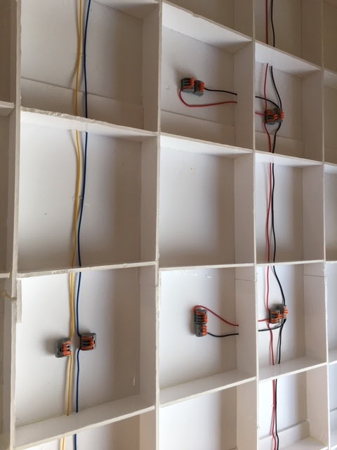
I also kitted out the 1 m2 board with the same busses. There will be a wander lead to connect both boards together electrically.

As you can see in the above image, there are two 1cm dowels fixed within the edge of the board. These fit into two holes in the main board. As the removable board sits on the dressing table, there is no need for anything more to keep them aligned. Remember that there is Märklin C track crossing the gap. C track is very robust so the physical rail connection is secure. Also, as the desk height can be altered, using the electric mechanism, the main desk is made to be at exactly the same height as the dressing table top. All I need is one removable leg to support the overhang and everything is tidy.
The next step was to install the powered uncoupler ramps. These need a DCC accessory manager. I chose the ESU Switch Pilot as my controller is an ESU product and I like what they do. Mind you, I couldn't work out how to change the accessory numbering from 1 - 4 and the manual printing size was for someone with the eyes of a 10 year old. A trip to Coastal DCC, where I bought the item, had Kevin reprogramming it for me to address 21 - 24, which keeps these away from my point assignments. It was me being thick as it was the same process as with the Cobalt motors that I used with my other layouts. The final wiring looked like this (the Switch Pilot is the black box along the bottom):

At this point, the DCC bus is connected to the track in three locations as well as the main connection from the ECOS. The last thing to do was to replace the curtains so that my wife wasn't offended by all my junk underneath the railway - grin. Mind you, the curtains don't quite reach so I need to sew some more - sometime!
Note: the curtains actually went up earlier so this picture is a bit on the premature side!

No comments:
Post a Comment