Monday, 28 October 2019

Planning the track layout

The idea of the new layout was to provide for a double track main line with one station and access to storage. This involved negotiating a further 1 square meter from my wife. If fact, she was quite amenable to the whole thing and gave up a part of her dressing table top to make the plan work. It also involved moving her bedside cabinet under the railway so overall she was very kind.

The extra real-estate was required because the outside track had to be R2 sized and this would result in a lot less room if I was to go the route using only the 2 square metres that I had previously. As it happened, the top of the dressing table (or at least the small amount that I had garnered) was great for supporting the new extension. I will show how it all looks later in the blog.

I now had to come up with a plan to use the new space. There were a few druthers (as our friends in the USA call them); i.e. wants rather than constraints. My three main wants were

  1. To have the double track main line
  2. To have access in both directions to the storage tracks
  3. To rationalise the station to suit a small terminus with a few local trains
The double track would also allow for main line trains to traverse and leave without any problems.

The track plan was worked out using Anyrail 6. Not everything connected perfectly but the minor issues shown up by the software were easily sorted with a bit of wiggle in the real world.

My first plan, and one that I actually laid, was as follows:


This provided for a two track passenger station, a goods arrival track and two local goods sidings.


There were two things wrong with this. Firstly, at A, there was no way to get any wagons into here unless the delivery loco pushed them there. The local shunter would always be on the wrong end. Secondly, the third uncoupler at the front of the second main track of the station would never be used, so it was moved to the third incoming line. I did think about putting a release crossover in but the available track left would be very short, plus I didn't have a budget for two more digital points!

My next attempt looked like this.


It now came to light, after running a few trains, that there was no way for a main line train with right hand running; i.e on the inside loop, to get back out to the wye to use the storage. This required a rethink. Fortunately, my friend Adrian - from whom I buy a lot of my Marklin stuff, came up with a  couple of points, motors and decoders so I could put a second crossover into the main line.


The above still shows the uncoupler in the wrong place but I sorted that as well. Now we have a layout where, using right hand running, there can be two trains on the main line and a shunter shunting in the yard. Admittedly, trains running on the inner track have to reverse run from the wye to the crossover at the rear. To avoid crashes, the crossover is protected by a colour light signal - the signal controls a dead section just in front of it so, when red, the track is dead. Additionally, any train that wants to leave the station must reverse run until they get back to that crossover.

It isn't perfect but it will let me run three types of train - main line leaving the wye to run clockwise; main line leaving the wye to go anti-clockwise and local trains leaving the wye to go to the station. I have had to create an extra name for the train routing. Pennstadt is clockwise, Valdorf is the station and, the new one, Hennersdorf is anti-clockwise. Pennstadt gets its name from our surname - Pennington; Valdorf from my wife's name - Valerie; Hennersdorf after my wife's favourite golden retriever, Henry (always known as Henners).

That's about all for now. Just note that the one square metre board is totally removable. Also, the main board can be rotated across the desk with the "dangling" end over the edge of the desk supported on two temporary legs. Thus, I can get to all parts of the layout whilst in my office chair - crucial given the state of my arthritis!

Finally, as promised, here are a couple of shots of the new extension. As you can see, it rests on the dressing table top. The basic support for the railway is an "electric" desk which supports the main board. This desk is 1600 x 800 in size and has an electric mechanism for raising and lowering the desk height. This was supplied to my by the Open University as part of their disability support when I was completing my B.Sc. This means that I can get the height of the desk to be exactly the same as the dressing table top. It makes everything nice and easy and very firm.


The separation line is along the demarcation between the brown and the white. The two holes in the top of the brown side are for power to the two fairground rides as the main open part of this board will be the fairground.

Tuesday, 22 October 2019

Building the basic layout

First steps, as always, are to build a decent baseboard and lay the track accurately. Following that, the electrics need to be put in place. I will deal with the steps in that order.

Making the Baseboard

I am relegated to one end of our bedroom. My wife doesn't mind this (or at least, so she says) as I have given up my hobby room so that her 93 year old mother can come and live with us. My wife's two passions are murder mystery novels and completing 1,000 piece jigsaws. She has her comfy armchair and a nice jigsaw workstation (with storage for her stash of 30 jigsaws!). Apart from a B.Sc. the only other thing that I got from the Open University was a large (1600x800mm) electric desk. By electric, I mean that the desk work surface can be raised and lowered as needed. My basic board is 2000 x 1000mm so there is about 200mm overhang at each end and 200mm at the back which is very workable.

I negotiated another 1 square metre when my wife offered that I could cover some of her dressing table. This really is a cooperation project as she likes to see the railway, when it has lighted houses and a fun fair, when she lays in bed! This gave me a nice L-shaped layout that would allow a double track continuous circuit, a small terminus with a goods yard and a wye going off to my storage board. This is a major leap forward from my existing - first attempt - layout.

Hobbycraft have a super offer - four sheets of 5mm foam core A1 sized for £10.00. Three packs will be enough so £30 is not a bad cost for the baseboard of a railway of this size. You may wonder at 5mm foam core but remember two things. One, I have very bad arthritis so cannot climb underneath and with a foam core build I can lift it up and work on the underneath with me sitting or standing up. Secondly, the firm base of the desk means that, so long as I do build a proper support structure underneath then everything will be OK. In fact, so long as I get the outer rim strong, the rest is really there to make sure that the flat boards don't warp. Anyway, that's how it goes.

The outer frame is made of  three ply 60mm strips. I make these as tongue and groove so the middle one is extended out one end, leaving a groove in the other. This makes butt joints very strong. With the last layout, I use three ply all over the underneath but the cross braces didn't add anything to the strength and just made the construction time longer whilst I made the strips. This time, I used single ply strips but, instead of at 12" spacing, I brought it down to 8".

This is the basic 2 x 1m board finished and in place.


The 1 x 1m extension was a bit more complicated as it needed to be cut back on the curves to lessen the bulk in the room. Hence, I needed to lay out the loops on a plain sheet to work out where to cut everything.


Above, you can see me carrying out this operation and laying the track.

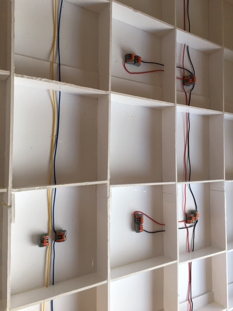
Once the track was down, I wanted to create some power busses under the board so that I didn't end up with a rats nest again. First off, I purchased some clever wire connectors.


As you can see  there are four connectors in this example. Place a wire in each hole and drop the lever gives very firm connections for almost any size of wire. This example is for the 12V bus. There is also a 5V and a DCC bus. These connectors come in a pack from Amazon (where else?). The pack contains connectors with 2, 3, 4 and 5 levers so they are very flexible.


I also kitted out the 1 m2 board with the same busses. There will be a wander lead to connect both boards together electrically.


As you can see in the above image, there are two 1cm dowels fixed within the edge of the board. These fit into two holes in  the main board. As the removable board sits on the dressing table, there is no need for anything more to keep them aligned. Remember that there is Märklin C track crossing the gap. C track is very robust so the physical rail connection is secure. Also, as the desk height can be altered, using the electric mechanism, the main desk is made to be at exactly the same height as the dressing table top. All I need is one removable leg to support the overhang and everything is tidy.

The next step was to install the powered uncoupler ramps. These need a DCC accessory manager. I chose the ESU Switch Pilot as my controller is an ESU product and I like what they do. Mind you, I couldn't work out how to change the accessory numbering from 1 - 4 and the manual printing size was for  someone with the eyes of a 10 year old. A trip to Coastal DCC, where I bought the item, had Kevin reprogramming it for me to address 21 - 24, which keeps these away from my point assignments. It was me being thick as it was the same process as with the Cobalt motors that I used with my other layouts. The final wiring looked like this (the Switch Pilot is the black box along the bottom):


At this point, the DCC bus is connected to the track in three locations as well as the main connection from the ECOS.  The last thing to do was to replace the curtains so that my wife wasn't offended by all my junk underneath the railway - grin. Mind you, the curtains don't quite reach so I need to sew some more - sometime!

Note: the curtains actually went up earlier so this picture is a bit on the premature side!


Wednesday, 9 October 2019

A new start

So, there was I, just idly chatting to my wife saying how much I like seeing trains pass each other and how this wasn't possible on my existing layout. "Well, take it down and start again" she said. This made some sense because of the way that the railway began.

I bought a Marklin train set and made some simple adjustments to the layout to fit onto my 2 x 1 metre space. I didn't give it much thought but now, looking at it, I can see the flaws. There were twin tracks where I could park one train whilst the other ran. I also put what has turned out to be a little used goods yard. What I realised that I wanted was a twin track run with a decent station for passenger trains and a small goods yard with a couple of factories rather than a three lane shunting yard with no need for that amount of wagons.

Out came Anyrail and I came up with the following.


Valerie agreed to a small, 1m square addition to the layout, which would cover some of her dressing table - remember that as mother-in-law lives with us, I have lost my railway room and now reside down the end of our, admittedly large, bedroom. The red line denotes the edge of my board and the wye feeds out to my detachable shadow station.  We now have a double track, access to a main station from the inner loops. The main station (Pennstadt) has two nice long reception tracks. There is also a couple of goods sidings and space for my V60 to hide away. There is also a head shunt to so that operations in the station won't interfere with the outer tracks. Hence, in theory, I could have three trains in operation at the same time! One of my Marklin friends suggested that I add another crossover to let the outer line access the station but this isn't how I want it to work. I am trying to use German right hand running so the outer track is for anti-clockwise and the inner for clockwise operations. This is fine except for a little bit of reverse running for the trains accessing the inner track from the wye around the bottom part of the outer loop.

I now realise that this running only works if the inner run enters the station where, coming out, it can process to the outer loop via the crossover at the top. If a train just traverses the loop and wants to come back out, there is no way without reversing. As an example, my crocodile with some SBB hoppers would have no reason to enter the station so, if travelling on the inner loop, would have an issue. I am now putting a crossover in to the left of the wye using left hand points so any train can pass the station entrance and still get out to the wye.

On the first layout, I took my wife seriously - "DON'T use a computer to run the trains!" was her comment. This meant that I only powered the points at the back of the layout where they were hard to reach. On discussion, she agreed that she didn't mean that quite so I have now got an agreement to power all of the points. Little does she know that the layout on the JMRI screen will just become one of the ECOS!

The layout was torn down - foam core is very light and easy to break up. We live in an apartment block and have a large bin room in the basement so the remains were quickly disposed of.  Our local Hobbycraft sells top quality A1 foam core at £10 for 4 sheets so that was a cheap way to get the new boards built. I had a small annual pension pay out in September and mother-in-law gave me a small bonus so I had all the funds that I needed. I put the plan together and ran up a track parts list. Working out what I didn't have was easy - I am a bit of a spreadsheet buff - and off went the requirements to my friend Adrian, who always has lots to sell at good prices! He was able to fill my needs so I was able to start. Being retired, I can dedicate lots of whole days to my railway so it will all go together very quickly.

Next, I will cover the construction of the boards and the wiring.


Saturday, 21 September 2019

Building the Faller Ferris Wheel

As the next step in the road to a fun fair, I have the Faller Ferris Wheel 140312; not cheap at £91.00.


However, it doesn't end there. As stated on the Gaugemaster web site - " The ferris wheel lighting set 180635 is required once and the replacement bulb set 180636 is required twice for complete lighting of all gondolas." It doesn't even end there as you need a 16VAC power supply. Costs? The power supply is £17.95 from Gaugemaster. Next, to save a bit of money, I went to Modelbahnshop Lippe - who are my goto Marklin suppliers in Germany. The list is as follows:

Faller 180629 - Synchronous Hobby Motor -20.90€
Faller 180635 - Lighting set - 36.11€
Faller 180636 - Replacement Bulbs x 2 - 29.22€

So, that is £76.00 + £17.95 plus the original £91.00 - comes to £184.95. Cheap?

The kits comprises 267 parts and is well moulded. If have built someFaller kits in the past and this is pretty much the same. Accurately moulded and nice to put together but the instructions are very complex and difficult to follow. They should be easy but I don't find them so.

Anyway, onto the build. First off, I tackled the gondolas. These have two fiddly little gates and a guard rail. Fortunately, my Methyl-Ethyl-Ketone -  MEK makes easy work of gluing these on - except, of course, some fell off later!


The next step was to construct the wheel. So that the gondolas can get some power, there are little brass collars that need to be inserted into each gondola location. Each side of the wheel then has some fuse wire to be applied. This is wound around each of the collars all the way around the wheel. What is obvious, but not stated, is that the wire must then be run down one of the struts and caught in the pivot by the supplied brass axle. Once this is done, the two wheel halves can be glued together.


The gondola umbrellas are then built up - the two legs of each light are fed through two previously glued pivots and the wires are then trapped by metal pins. These pins then form the supports for the gondola and act as pathways for the power to get to the bulbs.


This all sounds well and good but it didn't work for me. I found that the connection between the wheel and the gondolas was extremely flaky resulting in a lot of switching on and off in a random fashion as the wheel rotated. I asked for some advice on the Marklin forum but all that came back was to make sure that the gondolas were adequately weighted (I had found that out) and that the connections were secure - which I could never achieve.

Pretty soon after, some of the bulbs failed which left some of the gondolas in the dark. I was left with having to buy some expensive Faller replacement bulbs or think again. As there were now too few bulbs for the gondolas, I had to think again. I stripped all the lights out of the gondolas and then fixed two circles of wire around the wheel - one out at 110mm and another at 95mm. I can then wire the resulting bulbs between the wires to create a light show.


The next step was to set up the Arduino to manage the wheel and the light show. The idea was that the wheel would turn for two minutes with a flashing light show. It would then change to a mode for the stopping and starting. This means running for 4.62 seconds and then stopping for 2 seconds. This would simulate the gondolas stopping for the riders to get off. This would happen for 20 events and then it will start running again.

This is how it all went together.


From top to bottom - two relays - one to stop and start the wheel and one to stop and start the lights.
In the middle is the Arduino Nano - this  controls the relays and provides the 5V for the replay power.
The item at the bottom is a cheap voltage converter "buck" from Amazon. It accepts 12V IN and provides three outputs for each of 12V, 5V and 3.3V.

The ride motor is 16VAC whist the Arduino runs on 5VDC. I have a Gaugemaster 16V wall wart and a 12V 5a ps that is already in use for the other ride. The Gaugemaster one would drive the wheel and the lights whilst the 12V would be reduced to 5V using the buck. As the 12V is buried under the baseboard, I powered the Arduino from a 9V PP9 battery. The problem was that both the Gaugemaster unit and the PP9 had the same sized barrel connectors. During one of my trials, I managed to plus the 16V into the 5V socket. A nice pillar of smoke  rose from the buck so that was one of them plus an Arduino that were trashed! Fortunately, the buck comes in a pack of four, whilst the Arduino Nanos come in packs of 3.

Finally, as there were so few working bulbs, I decided to buy some replacement grain of wheat (GOW) bulbs from Railway Scenics. These are 12V bulbs that, it turns out, that they can't manage 16VAC. A couple instantly burnt out.  This means a reworking of the power so that the relay controls a 5V feed.

Where am I now? Well, I have replaced all of the bulbs and wired up the system for the new configuration. Unfortunately, it is now on hold as my wife has suggested that I rethink the whole Marklin layout and, maybe, start again from scratch. The theory goes that - as I didn't know anything about Marklin back in January - I could make a better job by starting again! I had already been thinking that I wanted to be able to run two trains at the same time rather than only one.


Saturday, 10 August 2019

Getting obsessive about little things

The last week or so has been full of silly things that really count for very little but take up a lot of time.

Push Pull fun

First off, I was getting to grips with my new cab control, push-pull passenger train. The problem is that the cab coach has a decoder installed to control the lights on the face of the coach. The loco headlights change, of course, with the direction of the train. This means that, when I reverse the direction of the train, only the loco lights change. I then have to change the direction of the cab coach lights and, quite often, I forget.

The answer would be for me to create a consist where the controller manages the lights on the train. However, whenever I built the consist - which wasn't easy because I couldn't find the manual so kept getting it wrong - the lights on the cab were always the same colour as on the loco. I tried about 10 times and finally went on to the ESU forum and asked the question.

Three days later, I had still not received an answer so had to tackle the problem again. I sat down with the train and the controller and one hour later I had cracked the problem.

I turned the loco around physically!

It is now sorted! When the loco has white lights, the cab has red and vice versa. (BTW, I never did get an answer! I did get told off for placing the question in the German forum but I didn't get an answer there either!).


Arduino Stress and Fun Fairs

I am currently building a fun fair to go into the empty area on the left hand side of the railway. I have a roundabout (Faller Polyp) and a Ferris wheel. I have motorised the Polyp (well, thought I had) and am building the other two little concessions that come with it. The plan is to motorise the roundabout and fit it with music. It will also be decorated with an LED light show. All of this is to be managed through a range of Arduino processors. I have mentioned my activities before but I should explain that, although I have been programming since 1975, I have never used the C language so have had to change my mindset a little. I thought that I was getting somewhere as I already had an Arduino Nano controlling the level crossing and had demonstrated the roundabout working with music.

Aside: an Arduino normally comes as a development kit. Plug the board into a computer, using USB, and the board gets powered. In addition, the PC connects to the Arduino through a COM port (or the equivalent on a Mac or Linux). This connection provides a pathway for the code to be installed on the board. In addition, there can be feedback of data from the board to a "serial monitor" window. 

OK, on to the fun and games. The fun fair needs a decent, independent, power supply(PS). I am fitting 12VDC motors into the Faller kits, replacing their 16VAC ones which are hard to drive and need a specialised PS.  I already had a Chinese 12V PS but it has a problem - the 240VAC input is is the same line of connectors as the 12V so extreme care is needed. To avoid any issues, I planned to place it inside a box. Because it was to be closed, I decided to fit a computer fan. These are 12VDC and I thought it would be easy to fit one in. However....

12VDC but fixed - that means that they only operate at or near 12V so anything less and they sit and stare at you. I built the box and everything worked fine. However, the fan made a distinct hum which I felt would become annoying if heard constantly from underneath the layout. The plan moved on. If I put an Arduino in the mix and have this read a thermistor (a heat sensitive resistor) I can turn the fan on as the temperature rose and and off as it descended. Days later, it was all working except the fan. I realised that the problem was that I was using the fairground code to run this. This speeds the motor up, runs it for a period of time and the slows it down. Off to Amazon to find a new fan. This time, |I bought one that advertised PWM as an ability. PWM is Pulse Width Modulation. This means interrupting the 12V for a length (very small) of time which, even though the voltage stays at 12V, the average voltage is less so the motor runs slower. I fitted this and, again, nothing. I checked against my roundabout and that still worked fine. It seems that the PWM  fan requires a special sort of power and data link which I couldn't be bothered to mess around with so decided that I could live with simple on and off depending on temperature. Still nothing!

After hours of messing about fruitlessly, I realised that I had a ground on the Arduino (from the computer) and another ground on the L298N (the L298N is the power board that uprates the power available from the Arduino to a level that can drive a motor). This isn't good practice so I ran a ground from the Arduino to the ground on the L298N and - bingo - everything worked. For some reason, without the proper ground, the L298N was only outputting around 7 volts. With the ground sorted, it was outputting 11.95V and off went the fan. As an aside, suddenly the funfair ride was spinning fast. It seems that it was getting 7 volts when I thought that it had 12!

The last messing about was getting all of this to work on a Nano. Nanos are fully working Arduino boards but the are designed for sitting stand alone with power, not connected to a PC. They are very cheap at 3 for around £10.00 on Amazon. They have a micro USB connector for programming but all the connections must be soldered rather than using the jumper leads as in the standard Uno Arduino. Yet again, I messed about for a few hours not sure if I had the software wrong or the wiring. Eventually, I ruled out the software and did a detailed review of the wiring. This sorted the problem and now have a working fan system. I need to work out a realistic cutoff as, today, it was 77 degrees in our living room so to test it, I had a cut off of 80 and pinched the thermistor to get it to rise. I guess that a cutoff around 70 would be OK in actual use.

Here is the current box, although I am going to rebuild it into a bigger box. As you can see, there are 6 12V DC outputs available.

This is the Chinese power supply. It isn't intended to be used in a public location.


Here are the importand component parts. The fan is obvious. The item in the middle is the L298N. This takes control signals from the Arduino and provides higher power at 12V DC. It also has PWM inputs so the speed can be controlled, provided that the motor can use it. The Amazon purchased 12V DC motor in the roundabout does so I can slow it down and speed it up. This isn't needed for the fan. The item to the right is the Arduino Nano placed on some printed circuit board. The L298N has a 5V output so I power the Arduino from that. All nicely arranged.


Tomorrow, I build a new box and then that is that. Back to building the funfair. My next job is to get a couple of shift registers working with 16 LEDs to provide the light show on the roundabout. The Arduino doesn't have enough ports to drive 16 LEDs so I have to use nice little integrated bit shift circuits. Luckily, I have an Arduino development kit and there are examples with code for all little things like this, thank goodness. YouTube is a big help as well. More tomorrow.

Wednesday, 24 July 2019

Music and a fun fair


Here is a video of a new addition to my layout.


This is the Faller HO Polyp fairground ride. It comes with an AC motor, which I have discarded and replaced with an Amazon sourced 12V DC motor with gearbox.

12V DC motor

This has been hooked up to an Arduino with complex components. One is an L298N H Bridge motor controller. The other is a DF Player Mini - plays mp3s from a micro SD card.

You can see the resulting mess on the prototyping board here

UserPostedImage


Basically, there are 10 rock and roll tunes on the SD card. The Arduino picks one at random and calculates its length in seconds from an inbuilt table. It the spins the motor up gradually for 14 seconds, runs the ride for the required length and spins it down for 15 seconds. It then delays for a random period and starts all over again. The idea is to recreate the ride that my wife remembers from Raphaels Park, Romford in the 60s when she was a teenager! The L298N is there to drive the motor as the Arduino doesn't have enough oomph. The power to the L298N comes from a Chinese 12V power supply in the pink box behind. This is the source of the hum. I am currently working on a thermistor driven Arduino to go inside the box and control the fan, which is what is making all the noise! Mind you, as it is 85F in my living room at the moment, now is not a good time to work out the settings!

Sunday, 21 July 2019

Arduino, Arduino, Arduino

In case you don't know, an Arduino is a little processor board that can control physical items connected either through digital (on-off) or analogue pins on its board. Up to now, I have used an Arduino to control the level crossing. I now have three more in various stages of completion for the following tasks:

  • Indicators of  arrival in the shadow station
  • Making the "Polyp" ride operate
  • Coordinating 60's rock and roll music to the "Polyp".

Shadow Station

Because of my arthritis, I can't turn to see the trains when they reach the end of the shadow station board and control the loco from the ECOS. The simple answer was to put up some visual indicator of position for each of the shadow station tracks. The final answer was to use light dependent resistors (ldr) buried in the track to control coloured LEDs on the fascia board beside the ECOS. After a lot of messing around due to a faulty ldr, it was all resolved and in place. LDRs are very expensive - NOT. £4.99 for 70! Once I replaced the dodgy one, everything works. I now have this nice little display in front of me where each track is aligned to a coloured LED which lights up when a loco moves over it.


The white light is just to show that it is working because, when there are no locos in the shadow station, all the lights are off so it is nice to have a pilot light.


As the shadow station is dis-mountable, there is a multi-way plug attached which connects to the main board. This plug can only be inserted in one direction. Mind you, I have to remember to unplug it when taking everything down!


Although this is the one for the level crossing, it shows you how the LDR is placed in the track. It is not at all noticeable.

Making the Polyp ride operate

The Faller kit for a fairground ride is called the "Polyp". It looks like our Octopus ride. My wife remembers going on something similar in her early teens at the Funfair in Raphael's Park in Romford. I think that she remembers "The Whip" where the boys from the ride would hit the brake in one of the compartments to make it swing round. As she say, she always remembers not only the ride but the music that was played. This was all the excuse I needed. First off, I have to make the ride operate. It comes with a motor but this is a simple 16VAC motor that can be turned on and off. It needs an AC power supply, which I didn't have. I had a nice 12V Chinese PS sitting there from an earlier attempt to put under-shelf LED lighting in my old railway room. I was able to get a nice little 12V motor and gearbox from Amazon and fit it instead of the provided one.


The problem was making a "lightweight" Arduino control a motor that would pull current in excess of the Arduino's capability. The answer turned out to be an L298N Dual H Bridge Stepper Motor Driver . This sits between the Arduino and the motor and provides the extra power required. It can also be controlled for speed and direction. Here is the L298N attached to the Arduino and wired into the motor. The pink box contains the Chinese PS as the 240V connections were somewhat exposed!


The Arduino program drives the motor for a period and then keeps it still for another - random - period when the whole things starts over again. Notice that it starts up slowly and slows down nicely at the end.


Now, we have the problem of the "rock" music. That's the next step.

Coordinating 60's rock and roll music to the "Polyp".

There are so many cheap add-ons for the Arduino that you can manage almost anything that you can think of. I have a little thing called a DF PLayer Mini which is a little board that wires into the Arduino and provides music off a mini-SD card. All for £3.50 or so. This little thing can manage up to 100 folders with MP3 files inside. It can be started, stopped, make a selection, etc. The trick is to get it working! I had to mess about for a good few hours trying to get the correct include files and the matching code until I hit on the right combination. 


Currently, I am running it through a Boombar Bluetooth speaker but I have a natty little AUX driven one coming. Along with all of this, I have got hold of a set of CDs for Dion and the Belmonts, Del Shannon and Eddie Cochran. Tunes from these such as "Runaway" and "The Wanderer" should provide a great background to the fair. 

Now to tie it all in


Now, the big problem! I have to make the Arduino running the ride drive the other one running the music. Amazingly, there is an include file called Wire which does all of this. Provided I keep to a single character, I can send it from one to the other. '0' to '9' should do for the tracks, 'G' for Go and 'S' for stop should make it all workable.

The ride will decide on a random tune. Both will know how long the tune is. The ride can tell the music which track and when to start it. They will both run for the length of the tune and then the ride will tell the music to stop. The ride will then wait a random time and it will all start again.

Needless to say, it will be a bit like Christmas songs in a shop! Hence, we change the tunes by refreshing the SD card and we can turn the whole thing off on demand. This is where an LDR comes in. Sitting on the ground in the fun fair will be a police car. When the ride is active, the police car will be over the LDR. To stop the ride, just pick up the car and move it sideways to expose the LDR. Job done!